
 English
  Spanish
  German
  Russian
  Italian
  French
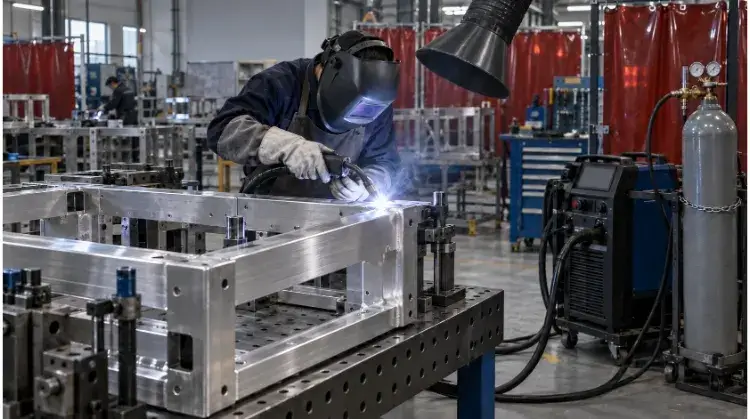
MIG welding aluminum requires a continuously fed aluminum wire (such as ER4043 or ER5356), 100% pure argon shielding gas, and a spool gun or push-pull system to prevent wire tangling. Success depends on pre-weld oxide removal and precise heat input to avoid burn-through on this highly conductive metal.
Unlike carbon steel, aluminum introduces severe thermal and wire-feeding challenges on the production floor. A slight variation in joint fit-up or inadequate surface cleaning leads directly to internal porosity, lack of fusion, and scrapped parts.
This guide explains how welders, engineers, and buyers can select the equipment, prepare the joint, set the process, diagnose defects, and verify weld quality before production.
Quick Aluminum MIG Welding Guide
| Parameter | Common Starting Point |
| Shielding gas | 100% argon |
| Polarity | DCEP |
| Common filler wires | ER4043 and ER5356 |
| Wire feeding | Spool gun or push-pull |
| Transfer mode | Spray or pulsed spray |
| Travel direction | Push technique is normally preferred |
| Main risks | Porosity, lack of fusion, cracking, and distortion |
| Consider TIG instead | Very thin parts, short precision joints, or critical visible welds |
These are starting points rather than universal rules. Final selections must match the alloy, joint geometry, thickness, welding position, and equipment capabilities.
Why Aluminum MIG Welding Is Different?
Treating aluminum like carbon steel leads to immediate equipment failures and weld defects. Aluminum requires different heat management and wire delivery methods due to its unique thermal properties and surface chemistry.
Oxide and Surface Contamination
Aluminum reacts with air to form a dense oxide layer. This layer melts at approximately 2,037°C, while the underlying aluminum alloy melts at roughly 660°C. If this oxide is not removed, it acts as an insulator, preventing the molten filler metal from fusing with the base material.
Moisture, cutting fluids, and oil trapped under or on top of this layer will cause porosity and lack of fusion. Because DC MIG welding does not provide the cathodic cleaning action found in AC TIG welding, pre-weld mechanical cleaning is mandatory. While proper shielding gas flow and a push torch angle help protect the molten pool, they cannot replace physical surface preparation. It is also critical to note that oxides are not the only source of defects; contaminated filler wire, excessive joint gaps, and shielding gas leaks cause identical fusion failures.
Heat Flow and Melting Behavior
Aluminum transfers heat roughly four times faster than steel. A cold workpiece requires high initial energy to establish a stable weld pool. However, as the surrounding material heats up, the metal absorbs less heat, rapidly increasing the risk of burn-through and distortion.
Because of this thermal conductivity, material thickness alone does not dictate the correct machine parameters. The overall size of the part, the tooling layout, and the available thermal mass change how heat dissipates during the welding cycle.
DFM & Cost Warning: Engineers must account for this rapid heat dissipation during the CAD phase. Specifying excessively tight dimensional tolerances on thin welded aluminum assemblies will inevitably drive up custom fixturing costs to control the resulting distortion.
Soft Wire and Unstable Feeding
Aluminum filler wire is inherently soft. Pushing it through a standard gun cable often results in wire shaving, blockages in the liner, and “birdnesting” at the drive rolls.
When wire feeding becomes restricted, it causes irregular wire speed and an unstable arc length, frequently leading to burnback inside the contact tip. Unstable feeding is more than an operational delay; fluctuating wire speed directly changes the actual welding current. This alters penetration depth and causes inconsistent weld sizes across the joint, leading to structural weak points.
Choose the Right MIG Welding Setup
Equipment selection depends on production volume, joint access, and process repeatability. Managing equipment constraints early reduces downtime and lowers the final cost per part.
Spool Gun Vs. Push-Pull
| Delivery System | Best For | Main Advantages | Main Limitations |
| Standard push | Short guns and limited use | Lower equipment cost | Highly sensitive to wire drag and cable bends |
| Spool gun | Maintenance, prototyping, and low volume | Short feed distance, simple setup | Heavy gun, frequent 1lb wire spool changes |
| Push-pull | Continuous welding and volume production | Stable feeding, utilizes large wire spools | Higher initial investment and maintenance |
ROI & Procurement Context:
A spool gun is cost-effective for short runs (e.g., batches under 50 parts). Push-pull systems become mandatory for continuous automated setups or annual volumes exceeding 1,000 units. At TZR, when we transitioned from spool guns to push-pull systems for our 5052 aluminum enclosures line, the reduction in wire-change downtime paid for the equipment upgrade within three months.
Note that while push-pull systems minimize feeding failures, they do not completely prevent birdnesting if drive rolls are set incorrectly or liners are severely worn.
Spray Vs. Pulsed MIG
| Factor | Spray MIG | Pulsed MIG |
| Average heat input | Higher | Lower |
| Typical thickness | Medium to thick sections (>3mm) | Thin to medium sections |
| Welding position | Mostly flat and horizontal | Better adaptability for out-of-position welds |
| Deposition rate | High | High and highly controllable |
| Burn-through risk | High on thin materials | Relatively low |
| Equipment cost | Standard CV machine | Requires advanced inverter power source |
Advanced dual-pulse programs add a secondary thermal cycle to the standard pulse. This regulates the heat input rhythm, refines the surface texture (mimicking a TIG appearance), and helps manage distortion on thin sheets. However, pulsed modes are not magic; they cannot compensate for poor joint cleaning, excessive root gaps, or incorrect wire selection.
Rollers, Liners, and Contact Tips
A stable aluminum wire delivery system requires specific consumables. U-groove drive rolls support the soft wire without crushing it, whereas standard V-groove rolls designed for steel will deform aluminum wire. Teflon or nylon liners are required to reduce internal friction inside the cable.
Aluminum wire expands as it heats, meaning contact tips must be sized specifically for aluminum (usually slightly oversized compared to steel tips) to prevent jamming. Gun cables must remain as straight as possible during operation to reduce drag. Finally, the spool brake tension and the push-pull motor balance must be adjusted so the wire feeds without excessive pulling force.
TZR Operator Tip: Increasing drive-roll pressure is not a reliable fix for poor feeding. Excess pressure will simply crush the aluminum wire out of round, making feeding problems significantly worse at the contact tip.
Match Wire and Gas to Aluminum
Selecting the correct filler metal and shielding gas dictates the structural integrity and corrosion resistance of the final weld. Visual guesswork leads to cracking, poor anodic coating matches, and joint failure.
ER4043 Vs. ER5356
Nearly 80% of aluminum MIG welding applications rely on either ER4043 or ER5356 filler wire. However, they are not interchangeable.
| Evaluation Factor | ER4043 (Al-Si) | ER5356 (Al-Mg) |
| Main Addition | Silicon | Magnesium |
| Wire Stiffness | Softer (prone to feeding issues) | Stiffer (more stable feeding) |
| Weld-Pool Fluidity | High | Relatively lower |
| Common Applications | Most 6xxx series joints (e.g., 6061) | Most 5xxx series and some 6xxx joints |
| Anodized Color | Turns dark gray/black after anodizing | Closely matches base material |
| Ductility | Lower | Generally higher |
| Elevated Temperature | Suitable for sustained high temps | Limited (Subject to stress corrosion above 65°C) |
Engineering Core Rule: Select filler metal by base-alloy compatibility and service requirements, not by tensile strength alone.
Base-Alloy Compatibility
Do not assume a filler wire works just because the base metals share a series number.
- 3003 / 5052 / 6061 / 6063: Generally highly weldable. Use ER4043 for ease of welding or ER5356 if the part requires color-matched post-weld anodizing.
- 5083 / 5754: High-strength structural alloys. ER5356 (or 5183) is required to match the mechanical properties of the base metal.
- 2024 / 7075: Aerospace-grade alloys. These are highly susceptible to hot cracking and are generally considered unweldable by standard MIG processes.
- Dissimilar Alloys: When welding a 5052 sheet to a 6061 extrusion, the filler metal must be evaluated against the chemistry of both base materials. (In this case, ER5356 is typically specified).
Argon and Helium Mixtures
100% Argon is the standard shielding gas for the vast majority of aluminum MIG welding, providing excellent arc stability and cleaning action.
Helium changes the arc profile, increasing voltage and heat input. Adding 25% to 75% Helium is usually reserved for thick sections to increase penetration and travel speed. However, using a Helium mix cannot compensate for cold base metal or insufficient machine power.
TZR Quality Control Note: Gas flow rates must be strictly monitored. Insufficient flow leaves the molten pool exposed to air. Conversely, flow rates pushed too high (usually above 35 CFH or 16 L/min) create a Venturi effect, pulling atmospheric oxygen and moisture directly into the shielding envelope.
Prepare Aluminum Joints Before Welding
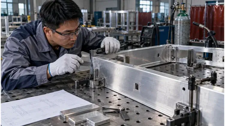
Contamination, poor joint fit-up, and inadequate tooling cause more aluminum weld failures than incorrect machine settings. Risk mitigation must happen before the arc is struck.
Cleaning and Wire Storage
Aluminum absorbs moisture and traps hydrocarbons easily. Standard operating procedures must follow a strict sequence:
- Verify material grade and temper.
- Remove oil, grease, adhesives, and cutting fluids using acetone or a dedicated degreaser.
- Wait for the solvent to flash off completely.
- Remove the oxide layer using a dedicated stainless-steel wire brush (brushing in one direction only).
- Handle parts with clean gloves during fit-up.
- Weld within 30 minutes. If the part sits longer, the oxide layer begins to reform and must be brushed again.
NDT Compliance Warning: Surface wiping might pass a visual inspection, but trapped hydrocarbons will immediately show up as subsurface porosity under X-ray (RT) or ultrasonic (UT) testing. Strict mechanical cleaning is the only way to pass aerospace or medical-grade non-destructive testing requirements.
Filler wire must be stored in sealed containers with desiccants. Never grind carbon steel in the same staging area where aluminum wire or cleaned aluminum plates are exposed.
Joint Design and Fit-Up
Consistent joint fit-up is critical because aluminum’s high thermal conductivity leaves a very narrow margin for error.
Excessive root gaps force the operator to slow down and dwell in the joint to deposit more filler. This drastically increases heat input, driving severe distortion in the final assembly. Furthermore, mismatched edges alter the penetration profile, creating stress risers.
DFM Cost Warning: Specifying oversized welds “just to be safe” exponentially increases heat input, resulting in warped parts that require expensive post-weld straightening operations. Specify the minimum required leg length to meet structural demands.
Fixtures and Torch Access
MIG welding aluminum requires a consistent 10° to 15° push angle to keep the shielding gas ahead of the weld pool. If a custom fixture or a deep corner prevents the gun from maintaining this angle, the weld will likely suffer from soot and porosity.
Additionally, heavy steel fixtures act as uneven heat sinks. A clamp placed too close to the start of a joint can draw heat away so rapidly that the weld suffers from cold lack of fusion at the tie-in.
Set Aluminum MIG Parameters Correctly
Copying a generic settings chart guarantees nothing. Machine calibration, travel speed, and joint geometry change the actual heat input. The goal is to establish a stable, repeatable process window through controlled test welds.
Starting Settings by Thickness
The following parameters serve only as a baseline for flat position welding using a standard CV (Constant Voltage) power source, 100% Argon, and ER4043 wire.
| Thickness | Wire Diameter | Transfer Mode | Voltage (V) | Wire Feed Speed (IPM) | Gas Flow (CFH) |
| 1.6 mm (1/16″) | 0.9 mm (.035″) | Spray | 17 – 18 | 250 – 300 | 25 |
| 3.2 mm (1/8″) | 0.9 mm (.035″) | Spray | 21 – 22 | 350 – 400 | 25 – 30 |
| 6.4 mm (1/4″) | 1.2 mm (.047″) | Spray | 24 – 25 | 300 – 350 | 30 |
Note: Final parameters must be verified through cross-sectioning or destructive testing prior to production. Do not treat this as a universal formula.
Note on Synergic Pulsed MIG: If your facility uses modern synergic inverters, manual voltage and WFS tuning is largely replaced by selecting the correct software algorithm (Synergic Line) for the specific alloy and wire diameter. Attempting to manually override these baseline curves often destabilizes the pulse rhythm.
Push Angle, CTWD, and Speed
Operator technique dictates whether the machine parameters perform as expected.
- Push Angle: Must be maintained at 10°-15° to break up oxides ahead of the puddle.
- CTWD (Contact Tip to Work Distance): Should typically remain between 15 mm to 19 mm (5/8″ to 3/4″).
- Travel Speed: Must outpace the heat transfer. Moving too slowly results in a wide, convex bead with poor root penetration.
Parameter Diagnostic Table:
| Weld Observation | Primary Variables to Check |
| Wire repeatedly stubs into the plate | Voltage too low, WFS too high, or CTWD too short |
| Arc becomes excessively long / wandering | Voltage too high or WFS too low |
| Bead sits high with poor toe fusion (Cold) | Heat input too low, travel speed too fast, or part acts as a heat sink |
| Wide bead with burn-through risk (Hot) | Heat input too high or travel speed too slow |
| Repeated burnback to the contact tip | Inconsistent wire feeding, worn tip, or fluctuating CTWD |
Process Control Rule: When troubleshooting, only adjust one variable at a time (e.g., change voltage by 0.5V, test, then evaluate). Changing voltage and wire speed simultaneously makes it impossible to isolate the root cause.
Vertical and Overhead Welding
Gravity aggressively pulls on a highly fluid aluminum weld pool. Standard spray transfer parameters used for flat plates will fail in vertical or overhead positions.
Out-of-position aluminum welding requires a controlled pulse program and a smaller weld pool, not simply lower machine settings.
The operator must rely on pulsed MIG to precisely control the droplet detachment and allow the puddle a fraction of a second to freeze. This requires coordinating travel speed, dwell time, and gun angle specifically for the joint’s orientation. Pre-production mock-ups in the actual welding position are mandatory.
Diagnose Aluminum MIG Welding Defects
Randomly adjusting voltage or wire speed rarely solves a defect. A systematic approach to troubleshooting isolates the root cause, preventing the same issue from halting the next production run.
Porosity and Black Soot
Aluminum absorbs hydrogen rapidly when molten. Any moisture, oil, or atmospheric air pulled into the arc will form porosity as the weld cools and solidifies.
| Defect Presentation | Common Causes | Priority Checks |
| Scattered Pinholes | Moisture, oil, or inadequate gas coverage | Base metal cleanliness, wire condition, and gas flow |
| Clustered Porosity | Localized contamination or solvent trapped in gaps | Joint fit-up and pre-weld cleaning sequence |
| Black Soot | Incorrect gun angle, long arc length, or turbulent gas | Nozzle condition, CTWD, and push angle |
| Internal Porosity | Hydrogen contamination or unstable shielding | Wire storage, liner condition, and gas line integrity |
🔍 TZR Troubleshooting Case:
We once chased a persistent internal porosity issue on a batch of 5052 aluminum tanks. After verifying the gas flow, base metal, and wire batch, we found the root cause: a worn Teflon liner was micro-shaving the wire, creating fine aluminum dust that trapped air inside the gun cable. Replacing the liner eliminated the porosity immediately. Always trace the entire path of the wire and gas.
Fusion, Burn-Through, and Distortion
A visually smooth, wide bead does not guarantee internal fusion. The weld pool can easily flow over the top of cold aluminum without actually melting into the root of the joint.
- Lack of Fusion: Usually caused by low heat input, moving too fast, or failing to remove the oxide layer. Weld width does not prove weld depth.
- Burn-Through: Often results from excessive root gaps rather than just high voltage. When operators slow down to fill a gap, the localized heat input spikes, melting the backing material away.
- Distortion: Adding voltage or dropping current are not universal fixes for warping. Distortion control must start with part sequencing, joint sizing, and rigid fixturing.
Cracks and Feeding Failures
Mechanical failures in the wire delivery system and thermal cracking in the weld metal account for the majority of production stops.
- Hot Cracking: Often caused by selecting the wrong filler wire (e.g., using 4043 on a high-magnesium alloy) or an overly concave weld profile.
- Feeding Failures: Birdnesting, burnback to the tip, wire shaving, and irregular feeding speeds point directly to drive-roll tension, liner health, or an incorrect contact tip size.
- Crater Cracking: Aluminum shrinks significantly as it cools. Abruptly stopping the arc leaves a deep crater highly susceptible to thermal shock and cracking. Modern equipment includes a built-in crater-fill function. If unavailable, operators must use the back-step technique or attach run-on/run-off tabs.
🛑 Workshop Rule: Stop welding the moment wire feed becomes irregular. Continuing to weld with a fluctuating arc creates inconsistent root penetration and makes the underlying cause much harder to trace.
Verify Aluminum Weld Quality
Quality verification proves the weld meets the structural and dimensional requirements specified on the drawing.
Visual and Dimensional Inspection
Every production run requires a baseline visual inspection. Inspectors must verify weld size, leg length, surface porosity, undercut along the toes, crater condition, and dimensional misalignment.
Engineering Boundary: Visual inspection can identify surface and dimensional problems. It cannot confirm complete internal fusion.
NDT and Destructive Testing
When structural failure carries severe safety or financial risks, internal verification is mandatory. Inspection methods must be determined by the part’s risk profile, engineering drawings, and applicable global welding codes—such as AWS D1.2 for the US market or ISO 10042 for European standards.
| Inspection Method | Primary Purpose | Main Limitations |
| Dye Penetrant (PT) | Detects surface-breaking cracks | Cannot detect internal porosity or hidden lack of fusion |
| Radiographic (RT / X-Ray) | Identifies internal volumetric defects like porosity | High cost and strict safety requirements |
| Ultrasonic (UT) | Locates internal defects in specific joint types | Highly dependent on material thickness and joint geometry |
| Macro-Etch Section | Verifies penetration, fusion, and weld profile | Requires cutting and destroying a test sample |
| Bend Testing | Tests joint integrity and ductility | Destructive test |
| Tensile Testing | Measures the load-bearing capacity of the joint | Requires standard test coupons |
WPS and Acceptance Criteria
Paperwork controls the repeatability of the process. These documents are not interchangeable:
- WPS (Welding Procedure Specification): The recipe. Defines the exact production parameters.
- PQR (Procedure Qualification Record): The proof. Confirms the WPS produces a weld that passes mechanical testing.
- Welder Qualification: The personnel check. Proves the operator has the skill to execute the WPS.
Before production begins, the buyer and manufacturer must explicitly agree on the base alloy temper, filler wire batch requirements, allowable joint gaps, permissible distortion, and the frequency of NDT sampling.
Design Aluminum Parts for Production
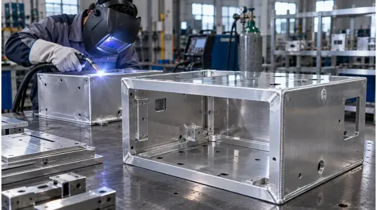
DFM (Design for Manufacturability) decisions made in the CAD phase directly dictate the final unit cost, strength, and rework rate of the welded assembly.
HAZ Softening and Design Strength
Unlike carbon steel, heat-treatable aluminum alloys (like 6061-T6) lose significant structural strength in the Heat-Affected Zone (HAZ) during welding. The intense heat reverses the alloy’s tempering.
The tensile strength of the filler metal does not represent the strength of the entire joint. Structural calculations must account for this localized weakened state. While post-weld artificial aging (heat treatment) can restore some strength, it rarely recovers the original T6 properties entirely.
Core DFM Judgment: Design for the expected as-welded strength unless a complete and qualified post-weld heat-treatment process is explicitly specified and budgeted.
Distortion and Process Repeatability
Aluminum expands roughly twice as much as steel when heated. If a designer specifies excessive weld sizes, the resulting heat input will warp the assembly beyond repair. Mitigation must be engineered into the process via balanced welding sequences, skip welding, heat sinks, and controlled interpass temperatures.
Manufacturing Reality: Distortion should be controlled through joint design, rigid custom fixtures, and automated sequencing before production begins. Relying on post-weld manual straightening (fixing it with a hammer) destroys production schedules and drives up unit costs.
MIG Vs. TIG Total Part Cost
Engineers frequently specify TIG welding out of habit, driving up costs unnecessarily.
| Evaluation Factor | MIG Advantage | TIG Advantage |
| Production Volume | Repeatable volume production and long continuous welds | Prototyping and low-volume batches |
| Thickness | Medium to heavy plates (>3mm) | Very thin sheets and delicate joints |
| Deposition Rate | High | Low |
| Access | Requires adequate physical clearance for the MIG gun | Torch can navigate tighter, more complex angles |
| Appearance | Acceptable (Pulsed MIG offers excellent aesthetics) | Easier to achieve precise, “stacked dimes” control |
| Heat Control | Good (with modern pulse algorithms) | Exceptional manual heat management |
Compare joint access, total weld length, production volume, finishing requirements, inspection levels, and the total landed part cost before defaulting to MIG or TIG.
💡 The TZR DFM Advantage: We don’t just weld what’s on the drawing. Before any production begins, our engineering team reviews your CAD files for excessive weld sizes and unoptimized joints, frequently saving our clients 15-20% in unnecessary manufacturing and post-machining costs.
Conclusion
- Reliable aluminum MIG welding begins with accurate alloy identification, rigorous mechanical cleaning, and compatible filler wire.
- Stable wire feeding and a verified, tested parameter window matter significantly more than copying a generic settings chart from the internet.
- Successful volume production requires defined joint geometry, agreed-upon inspection methods, and strict acceptance criteria established prior to the first arc strike.
Ready to move your aluminum project into production?
Send TZR your aluminum alloy grade, material thickness, joint drawings, and estimated annual volume. Our engineers will review filler selection, weld access, distortion risks, and NDT requirements to ensure a highly repeatable, cost-effective manufacturing strategy.