Thread Machining: Engineering Guide to Process Selection and DFM
Kevin Lee
Published:
Thread machining is typically one of the final operations in a CNC manufacturing cycle. A failure at this stage—such as a broken tap or a torn thread profile—often results in scrapping the entire part, wasting all previously invested machining time and material.
Selecting the appropriate threading method is an engineering decision driven by material yield strength, part geometry, and production volume. This guide explains how to choose between tapping, thread milling, and turning. It also covers key DFM guidelines that help connect rapid prototyping with mass production.
Thread Machining Process Selection
Threading Machining Methods
Different threading processes manipulate material physics in distinct ways. The optimal method shifts dramatically as a project transitions from low-volume prototyping to high-volume manufacturing.
Cut Tapping
Cut tapping removes material to create the thread profile, generating physical chips.
Application: Standard thread sizes in free-machining materials like carbon steel, cast iron, and specific aluminum alloys.
Considerations: Chip evacuation is the primary challenge. In blind holes, if chips pack at the bottom, the required cutting torque spikes, frequently leading to tool breakage.
Form Tapping (Roll Tapping)
Form tapping displaces material to form the thread profile through plastic deformation, rather than cutting.
Application: Ductile materials such as 6061-T6 aluminum, brass, copper, and low-carbon steel.
Production Advantage: This process generates zero chips, making it highly reliable for blind holes. The cold-working effect compresses the material’s grain structure, increasing the thread’s tensile strength. Because it runs at higher spindle speeds with lower tool wear, form tapping is the preferred method when scaling up to mass production for aluminum enclosures or heat sinks.
Thread Milling
Thread milling uses a rotating, multi-flute cutting tool moving in a helical path to machine the thread.
Production Advantage: This is the lowest-risk process. Because the tool diameter is smaller than the hole, chip evacuation is highly efficient. If a tool breaks, it drops out of the hole without scrapping the part. During rapid prototyping, thread milling offers maximum flexibility, allowing a single tool to cut different diameters of the same pitch.
External Thread Turning
Performed on a lathe, this process uses a single-point carbide insert matching the thread profile, taking multiple passes to cut an external thread.
Application: Standard for shafts, custom fittings, and cylindrical components requiring strict concentricity between the thread and the rotational axis.
Rolled Threads and Inserts
Rolled Threads: A cold-forming process where metal blanks are squeezed between hardened dies. It provides an uninterrupted grain flow, resulting in the highest possible strength. This is the ultimate mass-manufacturing process for external threads (like standard fasteners), driving the per-part cost down to fractions of a cent at scale.
Threaded Inserts (e.g., Helicoils): For soft substrates (such as aluminum or magnesium) subjected to high clamping loads or repeated assembly, directly tapped threads will strip. The standard engineering solution is machining an oversized hole to install a stainless steel threaded insert, providing a durable wear interface.
Process Decision Matrix
Use the following matrix to quickly align your threading requirements with the appropriate shop floor process:
Process
Best Material Application
Primary Advantage
Tool Breakage Risk
Ideal Production Volume
Cut Tapping
Free-machining steels, Cast iron
Fast cycle times, low initial tooling cost
High (in blind holes)
Low to Medium
Form Tapping
Aluminum, Brass, Mild Steel
Zero chips, stronger threads, long tool life
Low
Medium to High
Thread Milling
Stainless Steel, Titanium, Exotics
Zero scrap risk, high precision, flexible
Very Low
Prototyping to Medium
Thread Turning
Any turning-grade material
High concentricity, excellent surface finish
Low
Low to High (Lathe parts)
Thread Rolling
Carbon steels, Alloy steels
Ultimate strength, lowest unit cost
None (Die process)
High to Mass Production
Design Factors That Affect Thread Quality
Thread quality and final manufacturing costs are heavily influenced by the initial CAD model. Adhering to standard DFM guidelines prevents excessive tooling wear and significantly reduces lead times.
Hole Size and Minor Diameter
The pre-drilled hole size determines the thread engagement percentage.
Guideline: Design for 65% to 75% thread engagement.
Engineering Physics: Designing for 100% thread engagement is a common error. Moving from 75% to 100% engagement yields only a marginal ~5% increase in joint strength, but requires nearly three times the tapping torque. A 75% engagement provides optimal structural integrity while keeping machining forces well within safe limits.
Thread Depth
Guideline: Limit threaded depths to 1.5 to 2 times the nominal diameter (1.5xD to 2xD).
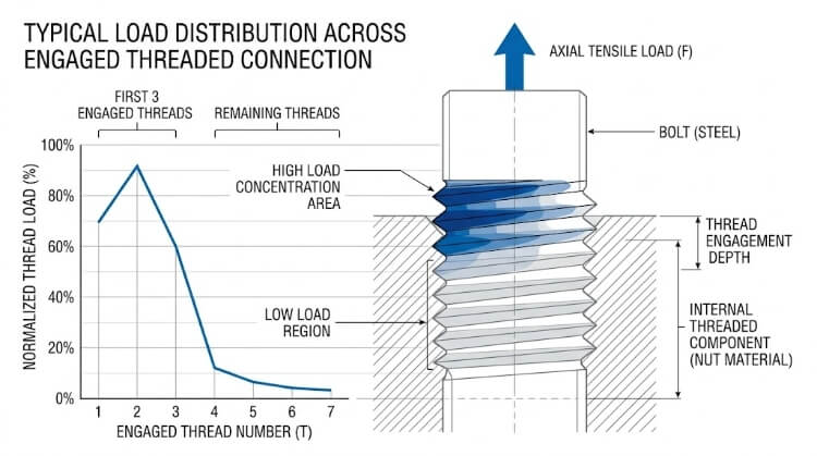
Engineering Physics: Mechanical load is not distributed evenly across a threaded joint. Due to pitch elongation of the bolt under tensile stress, the first three to four threads absorb up to 80% of the mechanical load. Specifying threads deeper than 2xD provides negligible additional tensile strength but exponentially increases the risk of chip packing, tool deflection, and coolant starvation during manufacturing.
Load Distribution Across Thread Engagement
Blind Hole Clearance
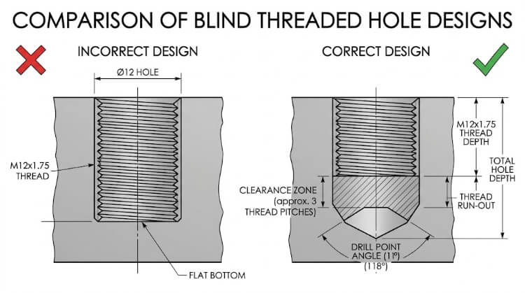
Taps cannot cut full threads to the absolute flat bottom of a drilled hole because of the chamfer on the tool’s leading edge.
Guideline: Design the initial drill depth to extend at least 2 to 3 thread pitches beyond the required functional thread depth.
Rationale: This unthreaded section provides necessary clearance for the tap chamfer to exit the cut and acts as a reservoir for compacted chips. If a tap bottoms out against the hole, it will shatter instantly.
Blind Hole Thread Design Incorrect vs Correct Bottom Clearance
Chamfers and Thread Entry
Guideline: Include a 90° or 120° countersink chamfer at the entrance of threaded holes, slightly larger than the major diameter.
Rationale: A chamfer physically guides the tap to center during tool entry, prevents material from displacing into a raised burr on the mating surface, and virtually eliminates the risk of cross-threading during final assembly.
Standard vs. Special Threads
Guideline: Default to standard coarse or fine pitches (e.g., standard Metric M-series or UNC/UNF) whenever possible.
Rationale: Specifying custom or non-standard thread pitches (e.g., M14 x 1.25 instead of the standard M14 x 1.5) requires the machine shop to source custom-ground tooling. This increases initial setup costs and typically halts production for 1 to 2 weeks while waiting for the tools to arrive.
Common Thread Machining Production Problems
Even with optimal process selection and DFM, thread machining introduces specific mechanical and thermal challenges on the shop floor. Understanding these failure modes is critical for engineers when evaluating a manufacturer’s capabilities or diagnosing rejected parts.
Chip Evacuation and Packing
Inefficient chip removal is the leading cause of catastrophic tap failure.
The Physics: In blind holes, chips that are not successfully evacuated will compress at the bottom of the bore. As the tap continues to feed downward, it impacts this compacted mass, causing an instantaneous spike in spindle torque that shears the tool.
Engineering Solution: Machinists dictate chip flow based on the tool geometry. Spiral point taps (gun taps) push chips forward and must only be used for through-holes. Spiral flute taps pull chips upward and out of the bore, making them mandatory for cut-tapping blind holes.
Built-Up Edge (BUE) and Galling
The Physics: During the machining of gummy materials (like aluminum or low-carbon steel), the combination of heat and pressure causes microscopic particles of the workpiece to friction-weld to the cutting edge of the tool. This “built-up edge” degrades the tool’s geometry, resulting in torn, oversized, or rough thread profiles.
Engineering Solution: Mitigating BUE requires reducing friction. This is achieved by using highly polished tools, specific coatings (like TiCN or TiB2), increasing coolant lubricity, and optimizing cutting speeds to shear the material cleanly before welding can occur.
Tool Wear and Pitch Diameter Drift
The Physics: Taps do not only fail by breaking; they wear down gradually. As the cutting edges abrade, the resulting internal threads become progressively smaller (tighter). If undetected, this drift results in threads that will not accept standard fasteners.
Thread Machining Troubleshooting Cheat Sheet
Below is a rapid-reference matrix for diagnosing and resolving common threading failures on the shop floor:
Symptom
Root Cause
Manufacturing Solution
Tap breaks during retraction
Chip packing at the bottom of a blind hole.
Switch to a form tap or a high-helix spiral flute tap; increase blind hole clearance.
Torn or rough thread flanks
Built-Up Edge (BUE) friction-welding to the tool.
Increase coolant concentration; switch to a polished/uncoated tap (for aluminum).
“No-Go” gauge threads all the way in
Oversized hole; tap runout/wobble.
Check spindle runout (TIR); verify pre-drill diameter; ensure tap is held in a precision collet.
Galling during final assembly
Mating parts cold-welding (common in stainless steel).
Ensure threads are clean; apply anti-seize compound; verify thread surface finish is below 63 µin Ra.
Special Cases in Thread Machining
Standard DFM guidelines must be adjusted when dealing with high-value exotic materials, extreme micro-features, or post-processing dimensional changes.
Austenitic Stainless Steels and Titanium Alloys
Materials like 304/316 stainless steel and Grade 5 titanium are highly susceptible to work-hardening.
The Cost of Failure: Titanium blanks and the initial roughing operations are highly expensive. If a tap breaks due to work-hardening on the final threading operation, a $500 aerospace component is instantly reduced to scrap metal.
Manufacturing Strategy: Tapping these alloys requires extremely rigid machine setups, sharp cutting edges, and Through-Spindle Coolant (TSC) to blast chips out of the hole and reduce thermal shock. However, to eliminate the financial risk entirely, thread milling is the mandatory process for high-value blind holes in these materials.
Micro-Threading (< M2 or #2-56)
Considerations: For miniature threads found in medical devices or aerospace electronics, cutting forces are minimal, but the tolerance for misalignment is virtually zero.
Manufacturing Strategy: The primary enemy of micro-threading is spindle runout (TIR – Total Indicator Reading). Even 5 microns (0.0002″) of wobble will snap a micro-tap. These features require ultra-precision collet chucks and frequently utilize “peck tapping” cycles (advancing and retracting the tool repeatedly to break chips safely).
Surface Finishing Allowances
This is one of the most frequent and costly oversights in engineering drawings. Post-machining treatments add physical thickness to the part, which directly alters the thread’s pitch diameter.
Quantified Impact: For example, Type III Hard Coat Anodizing (MIL-A-8625) typically adds 0.001″ to 0.002″ (25 to 50 microns) of thickness to all surfaces. In a standard M3 or #4-40 threaded hole, this build-up is enough to cause the mating fastener to seize completely.
Manufacturing Strategy: Engineers must specify the plating thickness and state whether thread dimensions apply before or after coating. The machine shop will then use oversized taps (designated by higher ‘H’ limits in the US, such as H4 or H5, or ‘6G’ tolerance classes in metric) to cut the thread larger than standard. Once the coating builds up, the final dimensions will fall precisely within the nominal specification.
Thread Inspection and Quality Control
Proving that a thread is geometrically compliant is as critical as machining it. Procurement and quality assurance teams rely on standardized metrology to verify thread forms before assembly.
Standard Verification: Go/No-Go Gauges
The industry standard for rapid, reliable thread inspection on the shop floor.
Plug Gauges (Internal Threads): The “Go” gauge verifies the maximum material condition (ensuring the pitch diameter is large enough and the thread is sufficiently deep). The “No-Go” gauge verifies the minimum material condition.
Acceptance Criteria: The “Go” gauge must thread completely through the designated depth by hand. The “No-Go” gauge must not engage more than two to three full turns before binding. If it threads further, the hole is oversized and the part must be rejected.
Precision Measurement: Pitch Micrometers and the 3-Wire Method
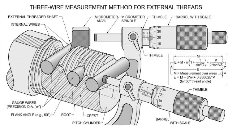
For external threads (such as custom turned shafts), simple ring gauges are often insufficient for statistical process control because they do not provide a quantifiable numerical value of tool wear.
Three Wire Measurement for External Threads
Metrology Application: Quality inspectors use thread pitch micrometers or the “3-Wire Method.” By placing three precisely ground wires into the thread grooves and measuring across them, inspectors use standardized trigonometric formulas to calculate the exact pitch diameter down to the ten-thousandth of an inch (0.0001″).
Automated In-Process Monitoring
In modern high-volume manufacturing environments, physical inspection of every thread is cost-prohibitive.
Quality Assurance Strategy: Advanced CNC machines utilize spindle load monitoring. The machine establishes a baseline torque curve during the threading of the first acceptable First Article Inspection (FAI) part. If the spindle load deviates from this curve by a specified percentage—indicating tool wear, chip packing, or a broken tap—the machine automatically halts production, preventing the manufacture of an out-of-tolerance batch.
Conclusion
Thread machining looks simple on the drawing, but the result depends on many details. The threading method, hole design, material, tool condition, and inspection approach all affect whether the thread works well in real production.
A good thread is not only one that can be cut. It should also run smoothly in assembly, stay consistent across the batch, and avoid avoidable scrap or rework. That is why thread machining should be reviewed early, especially for blind holes, small threads, difficult materials, and parts with finishing requirements.
Have a threaded part to make? Send us your drawing, material, quantity, and thread requirement. Our team can review the part, suggest a practical threading method, and point out any design or production risks before machining starts.
Wonderful! Share this Case:
Table of Contents
Send Your inquiry
Kevin Lee
Kevin Lee has over a decade of experience in the sheet metal industry, specializing in precision fabrication and problem-solving. With a strong focus on quality and efficiency, he brings valuable insights and expertise to every project, ensuring top-notch results and customer satisfaction in all aspects of metalworking.