
 English
 Spanish
 German
 Russian
 Italian
 French

Tool and die manufacturing is the industrial process of designing and building custom dies, fixtures, and templates used to cut and form raw materials—primarily sheet metal. It provides the critical engineering foundation required to mass-produce high-precision components with consistent tolerances.
In sheet metal stamping, the quality of your final part can never exceed the precision of your die. However,jumping straight into hard tooling isn’t always the right financial move.Whether you are an engineer optimizing a design for manufacturability (DFM) or a procurement manager calculating the total cost of ownership,this guide breaks down the real-world variables you must consider before approving a tooling project.
Here is a brief overview of the key principles:
- Tooling strategies depend on part geometry, design stability, and breakeven volume. Laser cutting remains cost-effective for runs under 5,000 units, while dedicated stamping dies typically justify their upfront cost when expected annual usage exceeds 10,000 units.
- Die quality relies on the precise coordination of multiple engineering stages. A die’s ability to hold strict tolerances is determined by part design, tool steel selection, CNC/EDM machining, and thorough tryout adjustments.
- Procurement must look beyond the initial quote. Sourcing decisions require comparing upfront tooling costs against piece-part prices, while factoring in die maintenance cycles, spare punch availability, and guaranteed tool life (e.g., 500,000 vs. 1 million strokes).
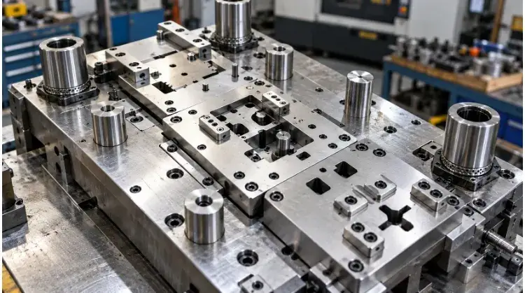
Understand What Tools and Dies Actually Do
Before evaluating production options, it helps to clarify the terminology used on the shop floor and understand how the equipment physically interacts with sheet metal.
Tools and Dies: Forming and Cutting the Metal
“Tooling” is a broad manufacturing term encompassing the various physical devices used to produce parts. In sheet metal stamping operations, it usually refers to the complete active die assembly rather than just passive holding devices.
A “die” is a specific classification of tooling designed to operate in a press to change the physical shape of sheet metal. For instance, a punching die shears the material to create a hole, while a bending die physically deforms the metal along a specific axis to create flanges or angles.
Jigs and Fixtures: Guiding and Locating
While sometimes grouped with dies, jigs and fixtures serve passive but critical functions. They do not physically alter the shape of the metal themselves, but rather support the manufacturing process.
A jig guides a cutting tool to a specific location, such as a drill bushing guiding a bit to ensure consistent manual hole placement. A fixture securely holds and locates a workpiece in a specific orientation, which is commonly used to ensure repeatability for secondary operations like CNC machining or robotic welding.
Main Die Components: The Anatomy of a Stroke
A typical stamping die relies on several core components working together in a fraction of a second. The punch (the male component) applies pressure to force the material into the die block (the female cavity), executing the actual cut or form.
The stripper plate holds the sheet metal flat during impact and pulls the material off the punch as it retracts. Throughout this motion, guide pins and bushings ensure the upper and lower halves of the die maintain exact alignment, which prevents edge chipping and maintains tight part tolerances.
Terminology and Structure Reference
| Term | Primary Function | Typical Application |
| Tool / Tooling | A broad category of physical devices used to manufacture parts | Umbrella term encompassing dies, molds, cutting bits, and fixtures |
| Die | Cuts or forms material under pressure | Sheet metal blanking, bending, drawing |
| Jig | Guides the manufacturing tool | Manual drilling, tapping |
| Fixture | Locates and holds the workpiece | CNC milling, robotic welding |
Choose Tooling That Fits Your Part and Volume
Selecting the right tooling approach is a matter of balancing the upfront engineering investment with production efficiency. The decision should be driven by specific part requirements and realistic cost projections rather than generalized industry assumptions.
Volume and Design Stability: Calculating the Breakeven Point
Total volume is important, but engineers must also evaluate the expected batch sizes, repeat order frequency, and the stability of the part design. If a part design is expected to undergo revisions within the next few production cycles, modifying a hardened steel die is expensive and causes significant downtime. For prototypes, short runs, or unstable designs, utilizing laser cutting combined with CNC press brakes is usually more cost-effective.
However, procurement teams should calculate the breakeven point to make data-driven decisions. If a progressive die costs $15,000 but reduces the piece price by $1.50 compared to laser fabrication, the breakeven volume is 10,000 units. If the design is locked and expected annual usage exceeds this threshold, dedicated dies become the logical choice.
Die Types: Matching Complexity and Output
There are several main die configurations, and the selection depends heavily on part complexity, required tolerances, and how the material needs to flow through the press. Single-station dies perform one operation per press stroke and require manual or robotic transfer. Compound dies perform multiple cutting operations in a single station, which works well for flat washers requiring high concentricity (often maintaining tolerances within ±0.05mm between internal features and outer edges).
Progressive dies feed a continuous coil of material through a sequence of stations, operating at speeds exceeding 60 to 100 strokes per minute to drastically reduce labor costs. Transfer dies operate similarly by moving the part through multiple stations, but the part is separated from the coil early and moved by mechanical transfer fingers. This method is usually used for deep-drawn parts where a continuous strip would restrict material flow and cause tearing.
Press Compatibility: Mitigating Shop Floor Risks
A precision die cannot function if it is incompatible with the stamping press. The engineering team must verify equipment specifications early in the design phase. Forming thicker or high-strength materials requires presses with higher tonnage and specific energy curves compared to standard mild steel.
The die dimensions must align with the press’s physical constraints, including the bed size, shut height (the clearance when the press is fully closed), and stroke length. Failure to account for these constraints can lead to setup delays or catastrophic die crashes caused by mismatched shut heights. The design must also account for how the coil material feeds in, how scrap drops through the bolster plate, and how finished parts are safely ejected.
Die Type Selection Guide
| Die Type | Suitable Part Characteristics | Material Feeding Method | Main Limitations |
| Single-Station | Simple cuts/bends, low to medium volume | Manual or robotic blanks | High piece-part labor cost, slow output |
| Compound | Flat parts requiring strict concentricity | Strip or coil feed | Limited to cutting (cannot handle complex forming) |
| Progressive | High volume, complex multi-step features | Continuous coil feed | High initial tooling cost, coil width restrictions |
| Transfer | Large parts, deep draws, complex geometry | Mechanical transfer fingers | Slower cycle times compared to progressive dies |
Improve Part Design Before Building the Die
Modifying a part’s design before cutting tool steel is the most effective way to reduce die costs and prevent production delays. Design for Manufacturability (DFM) adjustments focus on reducing tooling complexity and minimizing the risk of tool breakage during high-speed stamping.
Holes and Spacing: Preventing Material Distortion
When a punch shears through sheet metal, the surrounding material experiences significant stress. If holes are too small or placed too close together, the remaining webbing between them can warp or tear. As a general rule, the minimum hole diameter should be at least equal to the material thickness (1.0x T) for mild steel, or 1.2x T for high-strength alloys, to prevent punch snapping.
Similarly, hole placement relative to bends is critical. If a hole is located too close to a bend line, the material will pull during the forming process, distorting the hole into an oval. To maintain hole integrity, the distance from the edge of the hole to the start of the bend radius should be at least 1.5 times the material thickness plus the bend radius.
Bends and Draws: Standardizing Features
Every unique bend angle or radius on a part requires a dedicated punch and die section. Standardizing bend radii across the entire part (for example, keeping all internal radii at 1.0x T) reduces the number of unique tool components needed. This directly lowers the initial machining cost, simplifies future maintenance, and reduces the number of spare parts the stamper needs to keep in inventory.
For deep drawn features, the depth and the transition radii dictate how many progressive stations are required. Sharp internal corners require sharp radii on the die, which act as stress concentrators and lead to rapid tool wear. Using a generous minimum internal radius (e.g., ≥0.5x T) allows the metal to flow smoothly into the cavity rather than stretching and tearing.
Tolerances and Datums: Avoiding Over-Engineering
Tight tolerances should be reserved strictly for functional mating surfaces. Specifying a ±0.05mm tolerance on a non-functional bent flange will force the toolmaker to use tighter clearances and perform frequent grinding maintenance. This drives up both the die cost and the piece price compared to a standard ±0.2mm tolerance.
Establishing clear, stable datums is equally important. Datums should be assigned to unformed, stable features—such as a pierced hole on a flat surface—rather than a formed edge, which is inherently subject to springback variations. This ensures that part inspection is repeatable and reflects the true capability of the die.
Follow the Tool and Die Manufacturing Process
Building a die is a multi-step engineering project. It transitions from digital simulation to hard steel machining, culminating in physical tryouts to prove the tool’s capability.
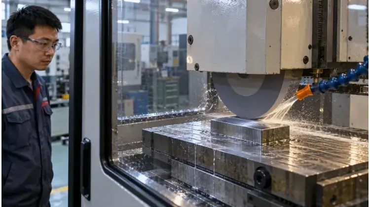
Die Design and Simulation
The process begins with strip layout design, which determines how the coil material will feed through each station to maximize material utilization and allow proper scrap ejection. At this stage, engineers calculate critical punch-to-die clearances, which typically range from 8% to 12% of the material thickness for mild steel.
For complex forming or deep drawing, tooling engineers use forming simulation software (such as AutoForm) before finalizing the CAD. This digital tryout predicts material thinning, wrinkling, and springback, allowing the team to compensate for these variables in the die geometry rather than relying on costly physical recuts later.
Materials and Machining
Tool steel selection depends entirely on the expected wear, shock impact, and required tool life. D2 tool steel, heat-treated to 58-60 HRC, is usually used for cutting components in medium-to-high volume runs due to its excellent wear resistance. For high-impact forming stations, A2 tool steel provides better toughness to resist cracking. For ultra-high-volume runs exceeding one million strokes, carbide inserts are often integrated into the die block to minimize sharpening frequency.
The machining sequence is structured to account for material deformation. Tool steel blocks are first rough-machined using CNC mills, leaving a small grinding allowance, and then undergo vacuum heat treatment. Because heat treatment induces slight dimensional changes, the final critical dimensions are cut afterward using Wire EDM (Electrical Discharge Machining) to achieve accuracies within ±0.005mm.
Assembly and Tryout
During assembly, toolmakers manually fit the components, checking alignment, guide pin clearances, and ensuring that stripper plates move freely. Once assembled, the die is loaded into a press for the first physical test, known as the T-0 (Tryout Zero) phase. The T-0 run rarely produces a perfect part; engineers evaluate the strip for feeding issues, measure the parts for dimensional accuracy, and check if scrap metal drops cleanly.
If a 90-degree bend exhibits 2 degrees of springback, the toolmaker removes the forming punch and grinds it to over-bend the material by exactly 2 degrees. These adjustments are verified in subsequent tryouts (T-1, T-2) until the die consistently produces parts that meet the drawing specifications. Because these mechanical adjustments require precision grinding and repeated press setups, the tryout phase typically accounts for 15% to 20% of the total tooling lead time.
Verify Quality Before Approving Production
A die might look perfect on the CAD screen and assemble flawlessly on the tooling bench, but its true capability is only proven under the stress of a stamping press. Establishing strict, evidence-based acceptance criteria prevents defective tools from entering your supply chain and causing downstream assembly issues.
Part Inspection: Beyond Basic Dimensions
Initial sample inspection must strictly align with the agreed-upon drawing revision and material specifications. Beyond checking critical tolerances, quality engineers must evaluate surface finish, flatness, and edge conditions.
For instance, shearing metal inherently leaves a burr. A standard manufacturing rule of thumb is that burr height should not exceed 10% of the material thickness. If the burr is larger, it indicates improper punch-to-die clearance or early tool wear. To eliminate subjective debates, rely on Coordinate Measuring Machines (CMM) and optical comparators to generate objective inspection reports mapped directly to the GD&T callouts.
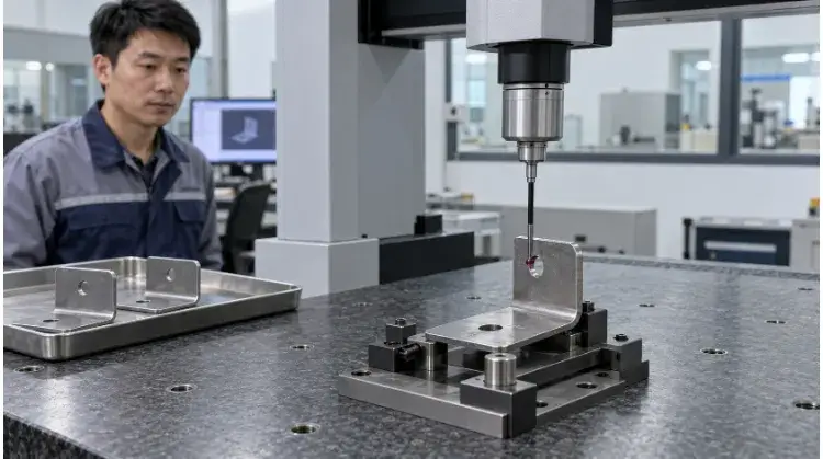
Production Trials: Stress-Testing the Tool
A die that produces a perfect part at 10 strokes per minute (SPM) during a manual tryout might fail catastrophically at 60 SPM in actual production. Production trials must replicate exact shop-floor conditions: the specific material coil, intended press tonnage, automated feeding equipment, and production-grade lubrication.
During the trial run, engineers watch for dynamic failures. They monitor strip feeding stability, verify that scrap slugs drop cleanly without pulling back up onto the die face (slug pulling), and record any abnormal press vibration. For critical dimensions, a 30-to-50 piece pilot run is often used to calculate Process Capability (Cpk). A Cpk ≥ 1.33 proves the die can maintain tolerances steadily over time without requiring constant operator intervention.
Acceptance Criteria: Defining “Done”
Procurement and engineering teams must agree on what constitutes a completed tooling project. There is a clear distinction between T-0 samples (the very first parts off the die, which almost always require dimensional tweaking), First Article Inspection (FAI) approval (parts perfectly match the drawing), and final mass production approval.
If a dimension fails during FAI, the protocol for tool modification, re-sampling, and re-inspection must be predefined. Standardizing this approval workflow ensures both the manufacturer and the buyer have a documented baseline before the final tooling payment is released.
Standard Tooling Acceptance Checklist
| Acceptance Item | Test Condition | Passing Criteria | Required Record |
| Dimensional Accuracy | Parts measured at room temp | 100% of critical dimensions within tolerance | CMM / FAI Report |
| Edge Quality | Visual & mechanical check | Burr height < 10% of material thickness | Visual Inspection Log |
| Dynamic Stability | Continuous run (e.g., 2,000 hits) | Smooth feeding, no slug pulling, no jams | Production Trial Video/Log |
| Process Capability | 30+ consecutive pieces | Cpk ≥ 1.33 for designated critical features | Statistical Process Control (SPC) Chart |
Evaluate Tooling Costs and Delivery Time
When comparing tooling quotes from different manufacturers, looking only at the bottom-line price is a massive risk. Procurement managers need to understand the cost breakdown, the long-term production implications, and the realistic timeline to avoid hidden expenses and delayed product launches.
Initial Tooling Costs: What the Quote Actually Covers
A tooling quote is much more than the cost of raw tool steel. Typically, high-precision machining (CNC milling and Wire EDM) accounts for 40% to 50% of the initial cost, while engineering design and physical tryouts consume another 20% to 30%.
Adding progressive stations for complex forms, requiring tight ±0.02mm tolerances, or designing multi-cavity dies (producing two or more parts per stroke) will drastically increase Wire EDM time and upfront costs. Always clarify what is included in the quote: Does it cover the raw material for the trial run? Does it include international shipping for the physical T-1 samples? Who bears the cost of tool modifications if the first samples fail?
Total Production Costs: The Hidden Impact of Maintenance
The true cost of a stamped part is the piece price plus the amortized tooling and maintenance costs—often referred to as the Total Cost of Ownership (TCO). Material utilization is a massive cost driver. If a poorly designed progressive die requires a wide carrier strip that wastes 40% of the coil, the long-term material waste will quickly eclipse any initial savings on the tooling price.
Furthermore, factor in tool maintenance. Stamping abrasive materials like stainless steel requires frequent die sharpening and replacement of wear components. A cheaper die built with inferior tool steel might save you $2,000 upfront but cost you thousands in unplanned machine downtime, expedited spare parts, and missed assembly line schedules over the first year.
Cost Scenario Comparison (Assumes 50,000 units EAU, locked design)
| Cost Driver | Laser Cutting + Press Brake | Progressive Stamping Die |
| Upfront Tooling Cost | $0 | $12,500 |
| Piece Price (Material + Labor) | $3.50 / part | $0.85 / part |
| Total Cost for 50,000 units | $175,000 | $55,000 (Tooling + Parts) |
| Verdict | Too expensive at this volume. | Saves $120k in the first year. |
Lead Time Drivers: T-0 vs. Mass Production
Standard tooling lead times range from 6 to 12 weeks, driven primarily by material sourcing, vacuum heat treatment, and slow-feed Wire EDM cutting.
However, buyers must distinguish between the “First Sample (T-0) Lead Time” and the “Mass Production Lead Time.” If a manufacturer quotes 6 weeks, that usually means the T-0 samples will ship at week 6. Reviewing those samples, executing design adjustments, re-grinding the tool, and running the final PPAP validation can easily add another 3 to 4 weeks. Furthermore, any mid-process design change initiated by the buyer will immediately pause machining and reset the delivery clock.
Typical Tooling Project Milestones
| Project Phase | Typical Timeframe | Key Milestone / Output |
| 1. Engineering & DFM | Week 1 – 2 | Final strip layout and 3D tool design approved |
| 2. Machining & Heat Treat | Week 3 – 5 | Tool steel cut, hardened, and finish-ground |
| 3. Assembly & T-0 Tryout | Week 6 | First physical samples (T-0) shipped for review |
| 4. Adjustments & T-1/PPAP | Week 7 – 9 | Tool fine-tuned; FAI passed; Ready for mass production |
Note: For international projects, always factor in an additional 3 to 5 days for expedited shipping (e.g., DHL/FedEx) of physical T-0 and FAI samples to your facility for final engineering review.
Conclusion
Evaluating tool and die manufacturing is about looking past the initial price tag to understand the total cost of ownership. The cheapest die on paper often becomes the most expensive tool on the press if it requires constant grinding, suffers from slug pulling, or delays your product launch due to endless tryout loops.
By prioritizing DFM before machining, selecting the right tool steel for your volume, and insisting on strict validation, you ensure that your tooling investment acts as a reliable engine for your production line.
Send the TZR engineering team your part drawings, material specifications, and expected production volume. Our team can review the requirements, calculate the breakeven points, and discuss a suitable, data-driven manufacturing approach.