
 English
  Spanish
  German
  Russian
  Italian
  French
A sheet metal part that functions perfectly in a CAD assembly does not always survive the press brake. This disconnect between digital modeling and physical fabrication is a common cause of production delays, high scrap rates, and unexpected cost overruns.
At TZR, our engineering team reviews hundreds of custom sheet metal drawings every month. We consistently see a pattern of design for manufacturability (DFM) issues that require revision before production can begin. Correcting a clearance issue in CAD takes minutes, but finding it during the First-Article Inspection (FAI) results in wasted material, new machine setups, and schedule delays.
To help engineering and procurement teams optimize designs for the shop floor, we have documented the nine most frequent sheet metal design mistakes and the standard manufacturing rules used to prevent them.
TL;DR: The 9 Sheet Metal DFM Mistakes to Avoid
- Mistake 1: Placing holes and cutouts inside the bending deformation zone.
- Mistake 2: Specifying multiple inside bend radii on a single part.
- Mistake 3: Ignoring press brake tooling clearance for complex folds.
- Mistake 4: Relying on complex welding jigs instead of tab-and-slot design.
- Mistake 5: Omitting bend reliefs at intersecting flanges.
- Mistake 6: Trusting CAD default K-factors without verifying material specs.
- Mistake 7: Failing to account for surface coating thickness in clearance fits.
- Mistake 8: Bending parallel to the material grain structure.
- Mistake 9: Designing large, hollow enclosures that increase shipping volume.
1. Placing Holes and Cutouts Inside the Deformation Zone
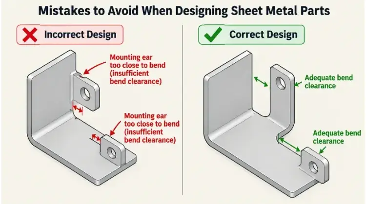
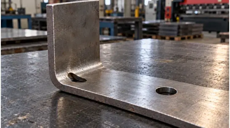
When sheet metal is formed on a press brake, the material immediately adjacent to the bend line undergoes plastic deformation. The inner radius compresses, while the outer radius stretches. If a hole, slot, or cutout is located within this deformation zone, the mechanical stress will distort the feature—typically pulling a round hole into an oval.
When this occurs, the part will usually fail incoming QC because fasteners will not seat correctly, causing misalignment during final assembly.
For example, if you are working with 2mm thick aluminum and a 2mm bend radius, the edge of any hole should be at least 7mm away from the start of the bend. If design constraints dictate that a feature must be closer, the manufacturer will need to drill or laser-cut the hole as a secondary operation after forming. This guarantees precision but adds cycle time to the manufacturing process.
2. Specifying Multiple Inside Bend Radii on a Single Part
CAD software allows designers to assign different bend radii to various flanges on the same part easily. While this might accommodate specific internal components or aesthetic preferences, it directly impacts shop floor efficiency and unit pricing.
Press brake operators rely on specific tooling combinations—a punch and a V-die—to form a designated radius. If a single part requires three different inside radii, the operator must stop the machine, change the heavy tooling, and run test bends three separate times. A single tooling changeover can add 15 to 20 minutes of setup time. Multiplying this across a production run reduces machine throughput and increases labor costs.
To keep production efficient and cost-effective, the standard practice is to specify a single, uniform inside bend radius across the entire part. A default radius equal to the material thickness (1T) is structurally stable and works well for most ductile materials, including cold-rolled steel and 5052 aluminum. For harder materials like 304 stainless steel, a 1.5T to 2T radius is generally recommended to prevent surface cracking.
3. Ignoring Press Brake Tooling Clearance (The “Z-Bend” Trap)
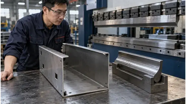
A common issue in sheet metal design is forgetting that parts are formed using physical machinery. While CAD software allows you to fold metal into tight, deep U-channels or compact Z-bends without issue, the shop floor requires physical clearance for the press brake tooling.
When a deep profile is formed, the previously bent flange can easily crash into the upper punch during the next bending sequence. Standard straight punches simply cannot reach inside deep profiles. Forcing a tight bend often requires custom gooseneck tooling, which immediately adds unexpected setup costs and extends your lead time by weeks.
If the part cannot physically fit around the tooling, the machine operator cannot complete the fold. Always design with the physical dimensions of standard press brake tools in mind.
4. Relying on Welding Jigs Instead of “Tab and Slot” Design
Traditional sheet metal assembly often involves joining two flat plates at a 90-degree angle using welding. To ensure exact perpendicular alignment and maintain tolerances, fabricators must build custom welding jigs. Designing and calibrating these fixtures adds significant cost and extends cycle times, especially for low-volume runs.
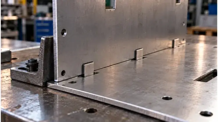
A much more efficient approach is integrating self-fixturing features directly into the flat pattern during the laser-cutting stage. By designing asymmetrical interlocking tabs and slots, you create a “Poka-Yoke” (error-proof) assembly.
Because the laser cutter naturally provides high precision, the tabs and slots fit together perfectly. It becomes physically impossible for a welder to assemble the parts backward. This method removes jig costs and reduces welding cycle times by up to 50%, becoming highly cost-effective at volume.
5. Omitting Bend Reliefs at Intersecting Flanges
When two bent flanges meet at a corner—such as on an electronic enclosure—the metal needs space to deform. If a designer attempts to fold these adjacent edges without removing material at the intersection, the metal will stretch and tear unpredictably.
These micro-tears and wrinkled corners are not just cosmetic issues or assembly bottlenecks. They expose bare metal, compromise protective coatings like zinc plating, and become primary failure points for rust and corrosion in the field.
Adding these small circular or rectangular relief cuts in the CAD file takes seconds but guarantees clean, structurally sound corners that pass QC inspections.
6. Blindly Trusting CAD Default K-Factors
The K-factor is a mathematical ratio that calculates how much a specific sheet of metal will stretch when bent. It is critical for generating an accurate flat pattern. Many engineers leave their CAD software set to the default K-factor (typically around 0.44 for mild steel) regardless of the material they are actually using.
The physical elongation properties of 5052 aluminum, 304 stainless steel, and cold-rolled steel are all different. If the software uses the wrong K-factor, the laser cutter will produce a flat pattern that is slightly off. Once bent, the final dimensions will consistently fail dimensional inspections.
Instead of guessing the K-factor, provide a clean 3D model with clear final tolerances. At TZR, our engineers calculate the exact bend deduction based on the specific material batch, grain direction, and the precise press brake tooling we will use for your run. This ensures your parts are dimensionally accurate from the very first article.
7. Failing to Account for Coating Thickness in Clearances
A CAD model represents bare metal, but physical parts almost always require a surface finish before final assembly. A frequent oversight is designing perfect clearance fits for hardware, moving mechanisms, or mating parts without calculating the physical thickness of the final coating.
Standard powder coating adds 0.06 mm to 0.12 mm of material per surface. If you design a hole for a tight press-fit PEM nut, that added thickness prevents the hardware from seating correctly. Sliding tabs or hinges designed with zero tolerance will completely seize up once the paint is applied.
Manually scraping away powder coat doesn’t just drive up labor costs—it compromises the protective finish and exposes bare metal, creating an immediate rust and corrosion hazard around your fasteners.
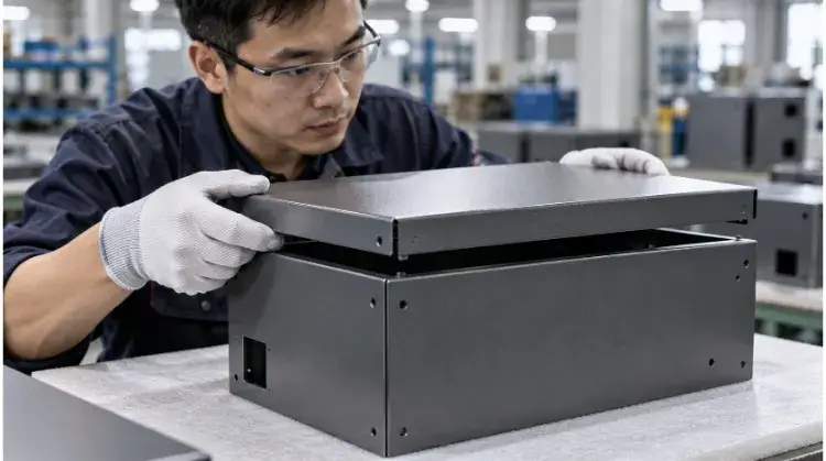
8. Bending Parallel to the Material Grain
Sheet metal is manufactured by running raw material through heavy rolling mills. This process elongates the crystalline structure of the metal, creating a distinct grain direction—much like the grain found in a piece of wood.
If you design a part where the bend line runs parallel to this grain, the press brake forces the metal to separate along its weakest structural boundaries. This routinely causes “orange peeling” or severe micro-cracking along the outer radius, particularly in harder materials like 304 stainless steel or 6061-T6 aluminum.
The small upfront savings in raw material utilization are instantly wiped out when a batch of parts cracks on the press brake and has to be scrapped.
9. Designing Large, Hollow Shapes That Ship “Air”
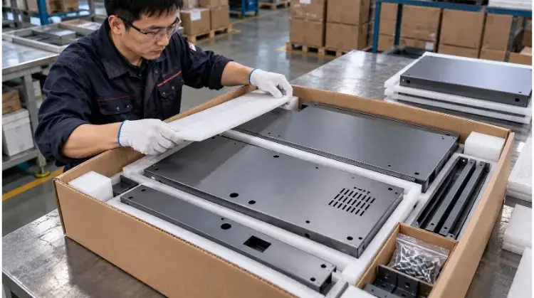
Procurement managers know that manufacturing cost is only one part of the equation; international logistics dictate the final landed cost. A common design failure for industrial equipment is designing large enclosures as massive, fully welded unibody structures.
Large, hollow assemblies have terrible nesting efficiency. They cannot be stacked densely inside an ocean freight container. When you ship these components, you are paying premium freight rates to transport empty air.
Beyond significantly lowering freight costs, flat-packing your sheet metal components effectively drops your transit damage risk to near zero.
Ready to manufacture your sheet metal parts? A quick review now prevents costly rework later. Send your STEP or DXF files to the engineering team at TZR. We’ll run a comprehensive DFM analysis, catch potential manufacturing traps, and send you a fully optimized quote within 24 hours.