
 English
 Spanish
 German
 Russian
 Italian
 French

Sheet metal folding is a manufacturing process that uses a press brake or CNC folding machine to plastically deform flat metal blanks into three-dimensional profiles along a straight axis. This guide covers forming methods, design for manufacturability (DFM) rules, bend deductions, and cost drivers.
Yet, understanding the basic process is only half the battle. Consider a standard four-sided flanged cabinet cover. Every individual bend angle might measure perfectly within the specified ±0.5° tolerance, but during the trial fit, the cover simply will not slide over the mating enclosure.
Issues like this occur when individual bend tolerances stack up and alter the overall assembly dimensions. A perfect CAD model means nothing if the shop floor cannot physically form it. Using this cabinet cover as a consistent example, this guide examines how equipment choice, drawing specifications, and layout decisions dictate the final fit and true production cost of your folded sheet metal parts.
Choose a Folding Method for Your Part
Before a supplier processes the flat pattern, they must determine the physical method used to form the flanges.
Press Brake and Folding Beam
The physical mechanics of forming dictate how the material behaves and how the operator must handle it.
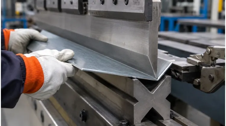
On a press brake, the flat sheet rests across a V-die. A top punch descends, pressing the material into the die cavity to create the angle. Because the punch pushes down, the flanking sides of the sheet metal sweep upward. The operator must physically support the weight of the sheet as it swings through the air.
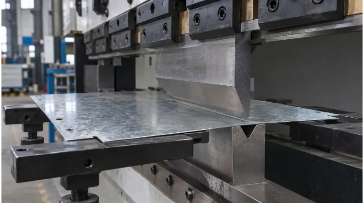
On a folding machine, the majority of the sheet rests flat on a support table and is held securely by upper and lower clamping beams. A pivoting folding beam then swings upward to bend only the protruding edge. The main body of the part remains stationary, meaning the operator does not need to lift or guide the bulk material during the bend.
Machine and Part Fit
Not every part is suitable for both machines. Suppliers review the part geometry against their available equipment to determine the most stable and cost-effective process.
For our four-sided cover, the engineering drawing dictates the material type, thickness, and dimensions, but the supplier chooses the machine based on practical constraints:
- Folding Machines: Work well for large panels because the machine table supports the part. They are usually used when surface protection is critical, as the folding beam causes less sliding friction against the material than a V-die.
- Press Brakes: Better for plate thicknesses exceeding 3mm, narrow U-channels, and complex geometries that require specialized punch profiles.
If the cover requires multiple flips to complete the four sides, the supplier must evaluate whether the tooling on either machine will clear the previously formed flanges without interference.
Check the Drawing for Folding Problems
A folding process is only as reliable as the drawing allows. Before cutting the first blank, the geometry must be checked for forming feasibility.
Inside Radius and Rolling Direction
The specified inside bend radius must serve two conflicting purposes: it needs to be sharp enough to leave clearance for the internal mating cabinet, but large enough for the supplier to form without fracturing the material.
Standard manufacturing data dictates the minimum safe bend radius based on material grade, temper, and thickness. As a general rule, mild steel can safely be bent to an inside radius of 1x material thickness (1t), while harder tempers like 6061-T6 aluminum often require 2t to 3t to prevent micro-cracking.
However, the rolling direction (grain direction) of the sheet metal introduces a critical variable. Bending parallel to the grain increases the risk of cracking.
Because our cover features flanges on all four sides, two of the bend lines will inevitably run parallel to the grain. To prevent cracking on those specific parallel bends, the supplier may need to increase the inside bend radius across the entire part, or source a more formable material condition (such as 5052-H32 instead of 6061-T6).
Short Flanges and Tool Clearance
When dealing with multiple bends on a single part, the sequence of operations limits what can be manufactured.
A four-sided box profile often presents tooling interference on the final bend. To form the fourth flange, the tooling must reach into the part without crushing the first three flanges. Furthermore, once the punch completes the stroke, there must be enough physical space to slide the enclosed part off the tool.
If the drawing shows flanges that are too short to span the V-die securely, or a profile too deep for the standard punch height, interference will occur. To resolve this, the supplier has a few options. Changing the bend sequence is free but not always geometrically possible. Using specialized segmented tooling (horn punches) works well for deep boxes, but adding 15 to 30 minutes to setup time directly increases the cost per part on low-volume runs. Modifying the flange dimensions on the drawing is often the most cost-effective solution if the assembly allows.
Hole Clearance and Bend Relief
Features placed too close to the bending zone will deform as the material stretches.
When a hole or slot is positioned near a bend, the plastic deformation of the material stretches the opening out of round. To avoid this, industry standard practice dictates placing the edge of the hole at least 2.5 to 3 times the material thickness plus the bend radius away from the bend tangent line (or a minimum of 3mm for very thin sheets). Additionally, adjacent flanges require corner bend reliefs. Without adequate width and depth in the relief notch, the material will tear at the corners when the adjacent sides are folded.
If assembly constraints dictate that mounting holes must remain strictly near the bend zone to align with the internal cabinet, the supplier cannot punch them in the flat pattern. The part must be folded first as a blank profile, and the holes machined afterward. While this preserves geometric tolerance, adding a secondary CNC routing or drilling operation can easily increase the part’s labor cost by 30% to 50%, especially on short runs.
Set the Blank Length and Bend Angle
Relying solely on CAD software for flat patterns often leads to dimensional assembly failures. Mastering bend deductions and springback compensation minimizes setup scrap and ensures accuracy.
Flat Pattern and Bend Deduction
To achieve the correct final dimensions, the flat sheet must be cut to a specific length before it reaches the press brake.
Consider a cover with a 50mm top face and a 30mm side flange, made from 2mm thick 5052-H32 aluminum. You cannot simply add the outer dimensions (50 + 30 = 80mm) to get the flat length. When sheet metal bends, the material on the outside of the bend stretches, while the inside compresses. The boundary between these two zones is the neutral axis, and its exact position within the material thickness is defined by the K-Factor.
Because the material stretches, the supplier must subtract a specific amount of material—the Bend Deduction (BD)—from the total outer dimensions. If the calculated bend deduction for a specific V-die and punch radius is 3.5mm, the actual blank length is 50 + 30 – 3.5 = 76.5mm.
Who owns the flat pattern? While design engineers often export flat pattern DXFs from their CAD software, the manufacturing supplier must always generate and confirm the final flat pattern. Bend deductions change depending on the exact tooling combinations used on the shop floor. If a buyer forces a supplier to laser-cut blanks using the exact engineering DXF without allowing adjustments for the shop’s specific tooling, the buyer effectively assumes responsibility for any final dimensional non-conformance.
Springback and Trial Bends
Calculating the flat pattern ensures the part has the correct amount of material. Setting the bend angle on the machine dictates the final geometry. These are two distinct adjustments.
When the punch presses the material into the die, it undergoes both elastic and plastic deformation. When the tooling releases, the elastic portion recovers, causing the flanges to open up. This is known as springback. To achieve the correct final dimension, the machine must overbend the part.
Using a consistent outside angle definition, the setup process looks like this:
- Target Angle: 90.0°
- First Trial Bend (Unloaded): The machine bends to 90.0°. Upon release, the material springs back to 92.5°.
- Compensated Bend (Re-measured): The operator adjusts the program to overbend to 87.5° under load. Upon release, the material springs back exactly 2.5°, resting at the target 90.0°.
Predicting springback is not an exact science. High-tensile materials like 304 stainless steel or hard aluminum tempers spring back far more unpredictably than mild steel. This means complex parts may require 2 to 3 setup blanks just to dial in the correct overbend. On a low-volume run of 10 pieces, the cost of this setup scrap heavily impacts the final price per part.
Verify Fit Before Releasing Production
Individual bend tolerances can easily stack up, causing perfectly measured parts to fail assembly. Rigorous first-article inspections catch these hidden interferences before full production begins.
Assembly Dimensions and Datums
Individual part tolerances do not guarantee assembly success. We return to the cabinet cover from the introduction: every angle measured within tolerance, but the part failed to fit.
This happens due to tolerance stack-up. If the drawing specifies a 90.0° ±0.5° bend, an actual part measuring 89.6° is technically acceptable. However, an 89.6° angle means the flange points slightly inward. If the flange is 30mm long, that 0.4° inward tilt on both sides reduces the overall opening width at the bottom edge by nearly 0.5mm. If the clearance between the cover and the mating cabinet was only 0.2mm, the parts will mechanically interfere.
To prevent this, engineers must clearly define the assembly dimensions using proper Geometric Dimensioning and Tolerancing (GD&T). Do not rely solely on individual bend tolerances. The drawing must explicitly state the critical internal opening width (e.g., 400.0mm +0.5/-0.0) as an independent inspection dimension, or apply a Surface Profile tolerance to the functional mating faces.
First-Part Inspection
Before running a production batch, the supplier performs a First Article Inspection (FAI) to verify the physical part against the drawing and the mating assembly.
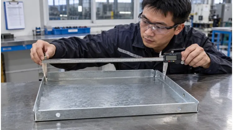
By placing the cover’s internal opening actuals next to the cabinet’s outer dimensions, we can identify exactly where the interference occurs.
| Feature | Drawing Requirement | Measurement Location | Actual Measured | Status |
| Cover Opening Width | 400.0mm (+0.5/-0.0) | Bottom inner edge of flanges | 399.5mm | FAIL (Interference) |
| Flange Angle | 90.0° ±0.5° | Center of side flanges | 89.6° / 89.7° | PASS |
| Mounting Hole Centers | 380.0mm ±0.2mm | Datum A to hole center | 380.1mm | PASS |
| Cosmetic (A-Side) | No visible tooling marks | Outside visible faces | Clean | PASS |
In this scenario, the angle passed, but the functional opening failed. The supplier must adjust the bend compensation to push the angle closer to 90.2° to open the clearance. Additionally, the cosmetic requirement is explicitly checked. If the drawing designates the outside face as an “A-Side” visual surface, the supplier will use urethane die tape or specialized non-marking lower tools to prevent the V-die from leaving witness lines.
For procurement managers, timing is critical here. If the drawing requires customer sign-off on the FAI before the full batch runs, the press brake sits idle. Delays in FAI approval often force the supplier to tear down the setup, meaning you ultimately pay for the machine setup time twice. Establish clear, rapid approval protocols to keep production moving.
Compare Quotes for the Same Folding Work
Supplier quotes often hide differing assumptions about tooling fees, secondary operations, and inspection standards. Standardizing your RFQ ensures you compare true production value, not baseline estimates.
Setup and Per-Part Cost
Manufacturing costs break down into two distinct categories: one-time setup fees and recurring per-part labor.
Setup includes offline programming, installing the V-die and punch, and running two to three scrap blanks to dial in the springback compensation. These are fixed costs. Recurring costs involve the physical handling of each part—such as the operator loading the blank, executing four separate bends (flipping the part each time), applying urethane die film for cosmetic protection, and performing secondary CNC drilling.
For low-volume runs (e.g., 10 parts), the setup cost is often applied as a flat Lot Charge, which heavily skews the unit price. At a production run of 1,000 parts, this setup cost amortizes to pennies, making the recurring machine time and physical handling the primary drivers of your final bill.
RFQ Checklist
To receive accurate, comparable pricing, your Request for Quote (RFQ) must leave no room for supplier assumptions. A complete RFQ package for folded sheet metal should include:
- Material Specifications: Exact grade and temper (e.g., 5052-H32, not just “aluminum”) and sheet thickness.
- Volume & Batching: Total annual quantity and expected release sizes.
- Critical Datums: Explicitly call out the assembly dimensions (like the cover’s internal opening width) that dictate function.
- Surface Finish: Specify visual requirements and whether cosmetic protection is mandatory during forming.
- Packaging Strategy: Sheet metal boxes ship a lot of empty air. Specify if parts should be fully folded and palletized, or if the design allows for flat-shipping and final assembly on your end to optimize ocean or air freight costs.
- Inspection Requirements: State clearly if you require a First Article Inspection (FAI) report before full production runs.
When providing both a finished 3D model and a flat pattern DXF, the RFQ must explicitly state that the finished part drawing governs quality acceptance. The supplier remains responsible for calculating the final bend deductions and adjusting the blank layout for their specific tooling.
Quote Comparison
When reviewing bids for the cabinet cover, comparing the bottom-line unit price without reading the line-item assumptions is a major procurement risk. You must evaluate the manufacturing process behind the numbers.
| Line Item | Supplier A | Supplier B |
| Unit Price (Qty 500) | $12.50 | $15.80 |
| One-Time Tooling / Setup | $150.00 | $280.00 (Includes custom horn punch) |
| Hole Machining | Laser cut on flat blank | CNC drilled after folding |
| Surface Protection | Standard V-die (witness marks possible) | Urethane die tape included |
| FAI Report | Standard dimensional check | Full GD&T layout |
| Lead Time | 12 Days | 15 Days |
Supplier A quotes $12.50 by punching the mounting holes on the flat blank before folding and using standard tooling. This is cheaper, but as established earlier, holes placed too close to the bend line will stretch and deform during forming.
Supplier B quotes $15.80 because they mapped out a secondary CNC drilling operation after the folding is complete to guarantee hole concentricity and alignment with the mating cabinet. They also factored in urethane tape to meet the A-side cosmetic requirement and a custom horn punch to clear the final flange.
Choosing Supplier A saves $3.30 upfront but introduces a massive Cost of Poor Quality (COPQ). If 20% of the covers fail to fit during final assembly, the true cost of Supplier A’s parts—factoring in scrap, assembly line downtime, and rework—far exceeds Supplier B’s $15.80 engineered solution.
Ready to move from design to production? Stop paying for setup scrap, hidden freight costs, and assembly line failures. Send your CAD files to TZR for a rigorous DFM review. Our engineering team provides transparent, line-item quotes built to international standards, ensuring your sheet metal parts fit the first time, every time.