
 English
 Spanish
 German
 Russian
 Italian
 French

To cut sheet metal fabrication costs, engineers must standardize material gauges, unify bend radii, relax non-critical tolerances, and minimize manual welding. Optimizing flat patterns for material yield and designing for standard press brake tooling directly reduces machine setup time and overall manufacturing expenses.
When reviewing hundreds of CAD files on the factory floor, we see the same pattern: up to 80% of a part’s manufacturing cost is already locked in before the metal is even cut. High quotes are rarely about the factory’s profit margins; they are usually driven by minor design choices that force operators to perform extra tool changes, run slower machine cycles, or scrap non-conforming parts.
Before modifying your design, you need to understand where your budget is actually going. Cost drivers shift depending on your part geometry and order volume.
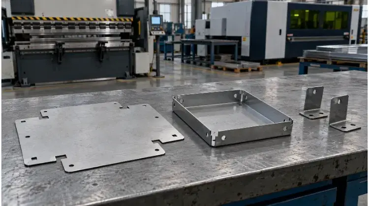
1.Choose Common Materials and Stock Sheet Thicknesses
Specifying materials that exceed functional requirements or are difficult to source routinely increases base costs and lead times.
Material Requirements
Select materials based on actual operating environments, strength, and weight requirements. When comparing material alternatives, calculate the total cost—including necessary surface treatments and fabrication effort—rather than just the raw sheet price per kilogram. For example, a more expensive pre-galvanized sheet may cost less overall than fabricating a cheaper cold-rolled steel part that requires post-process zinc plating.
Stock Thicknesses
Verify the grades, tempers, and thicknesses your fabrication partner routinely stocks. Using readily available materials prevents minimum order quantity (MOQ) premiums and material sourcing delays. Clearly specify the standard gauge or decimal thickness on your manufacturing drawings to avoid purchasing confusion.
Structural Stiffness
Evaluate if a thicker material is strictly necessary for rigidity. Often, a thinner gauge sheet reinforced with formed flanges, hems, or ribs can achieve the required structural stiffness. When considering this approach, compare the material savings against the cost of the additional forming operations.
Example Application:
Consider an internal mounting bracket originally designed in 3.0mm 304 stainless steel. If the operating environment is dry and indoors, switching to a 2.0mm mild steel with a bent flange and a standard powder coat usually reduces material costs significantly, as stainless steel can cost 3 to 4 times more per kilogram than mild steel. The engineering team simply needs to re-validate the new design for the required load-bearing capacity.
2.Improve Flat Patterns and Reduce Cutting Work
Inefficient flat pattern designs reduce material yield (how many parts fit on a standard sheet) and increase laser cutting or punching time.
Blank Dimensions
Check if non-critical overall dimensions limit the number of parts that can be nested on a standard sheet. Adjusting a non-functional length or width by just a few millimeters can sometimes allow an extra row of parts to fit on the raw material, which directly lowers the per-part material cost.
Nesting Constraints
Part rotation, mixed-part nesting, and spacing directly impact material yield. However, keep in mind that nesting efficiency is often restricted by material grain direction. If a part requires bends parallel to the grain to prevent cracking, or needs a specific cosmetic brushed finish direction, the fabricator has fewer options for rotating the part to optimize the sheet layout.
Cutting Paths
Review the design for overly complex profiles, dense clusters of small holes, and unnecessary internal cutouts. Laser cutting costs depend heavily on the total cutting distance and the number of pierces (where the laser first breaks through the material). For instance, replacing a dense grid of small ventilation holes—which requires dozens of individual laser pierces—with a few larger slots or specifying a standard punched louver can dramatically reduce machine cycle time while retaining necessary airflow.
3.Simplify Bends and Use Standard Press Brake Tooling
Complex bending requirements force fabricators to perform multiple tool changes, flip heavy parts manually, or order custom press brake tooling, all of which drive up labor and setup costs.
Bend Radii
Every unique bend radius requires a press brake operator to stop the machine, remove the punch and die, and install a new set—a process that typically adds 15 to 30 minutes of setup time per radius. Standardize bend radii across the entire part whenever functionally possible. Ideally, match the inside bend radius to the material thickness, which works well for standard factory tooling.
Bend Sequence
Review the bending orientation and sequence. Designing bends in multiple directions requires operators to repeatedly rotate and flip the part. For large or heavy sheet metal panels, flipping requires a second operator or a crane, slowing down the cycle time. Keep bends in the same plane and orientation where practical so the machine can process the part in a single, continuous flow.
Tool Clearance
Complex profiles like short flanges, deep U-shaped boxes, and return bends often cause tool collisions, where the press brake punch crashes into a previously bent side of the part. This forces the factory to use expensive specialized tooling (like gooseneck punches) or split the part into multiple pieces. Ensure the flange length is at least four times the material thickness (a standard rule of thumb for typical V-die openings) and leave enough clearance for standard tooling to access the bend line.
4.Reserve Tight Tolerances for Critical Assembly Features
Over-tolerancing is a common source of hidden costs. Applying a blanket tight tolerance across an entire drawing forces the factory to use slower processing speeds and mandates time-consuming inspection methods.
Functional Dimensions
Identify which dimensions actually affect assembly, fit, and function. While a ±0.05mm tolerance may be necessary for a press-fit bearing hole, applying that same strict tolerance to the outer decorative edge of a bracket is unnecessary. Use standard block tolerances (e.g., ±0.2mm) for general dimensions and only assign tight tolerances to mission-critical mating features. When a factory sees unachievable or globally tight tolerances on a print, they automatically bake a “scrap tax” into your quote to cover the parts they know they will have to throw away.
Tolerance Stackups
Sheet metal stretches and springs back during forming. Expect roughly ±0.15mm to ±0.2mm of variation per bend. If a part has four consecutive bends, the final dimension could vary by nearly a millimeter. Instead of forcing the fabricator to hold tight tolerances across multiple bends, use slotted holes or oversized clearance holes for fasteners to absorb the natural tolerance stackup during assembly.
Inspection Conditions
Clearly define measurement datums, inspection steps, and part conditions on your drawings. Measuring a flexible, thin-gauge sheet metal part from a sheared edge versus a laser-cut hole often yields different results. Clarifying how the part will be inspected reduces disputes and prevents the factory from pricing in additional rework risk.
5.Combine Parts to Reduce Welding and Assembly
Welding is highly skilled labor and one of the most expensive manual operations on the shop floor. Consolidating multiple components into a single bent part is a standard cost-reduction method, though it must be evaluated carefully.
Part Consolidation
Compare a multi-piece welded assembly against a single-piece bent design. A single folded part eliminates welding time, removes the need for assembly alignment fixtures, and lowers your overall Bill of Materials (BOM) management costs by reducing the number of individual SKUs and fasteners you need to source and track.
Forming Limits
Check if part consolidation creates new manufacturing bottlenecks. Sometimes, merging parts results in a massive flat pattern that wastes material, or creates a geometry so complex it causes tool interference on the press brake. In these specific cases, a two-piece welded assembly may actually be more cost-effective. Always include the cost of material yield and forming difficulty in your comparison.
Weld Requirements
When welding is unavoidable, specify the exact requirements. Do not ask for continuous seam welds if intermittent stitch welds provide enough structural integrity. Be explicit about cosmetic requirements; grinding and polishing a weld flat to match the surrounding surface often costs more than the welding process itself.
Example Application:
Compare a bracket made of two separate plates welded at a 90-degree angle versus a single piece of sheet metal bent to 90 degrees. The bent bracket eliminates welding and grinding. However, if the bent version requires a piece of sheet metal so large that it drops the material yield from 80% to 40%, the welded version might remain the cheaper production plan.
6.Add Locating Features to Simplify Multi-Part Assembly
When a design must remain a multi-part assembly, the way those parts fit together directly influences the labor time required for welding, riveting, or fastening.
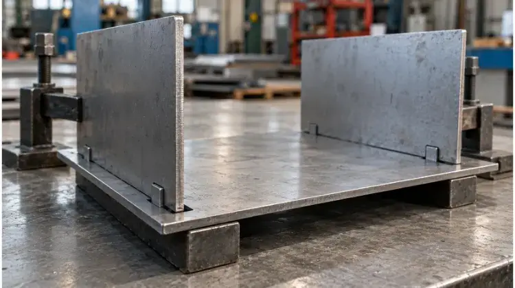
Tabs and Slots
Do not rely on operators to manually align parts with tape measures and custom clamping jigs. Incorporating “tab and slot” features into the laser-cut flat patterns allows parts to self-fixture (poka-yoke). This error-proofs the assembly and eliminates the need for custom welding fixtures, which can cost hundreds of dollars and add weeks to your lead time. When designing these slots, remember to account for the laser kerf (cutting width) and any additional thickness from plating or powder coating to ensure the tabs actually fit together.
Tool Access
Check the CAD model to ensure welders, riveting tools, and wrenches have physical space to access the joints. Designing blind corners or extremely narrow channels forces workers to use specialized tools or perform awkward, slow operations, which drives up assembly labor costs.
Standard Hardware
Use common, standard hardware like PEM nuts, standoffs, and studs instead of manually welding standard nuts to the sheet metal. Self-clinching hardware is installed quickly with a press, offers excellent pull-out resistance, and eliminates the heat distortion and grinding cleanup associated with welded fasteners.
7.Limit Cosmetic Work and Specify Finishes Clearly
Ambiguous surface finish requirements or unnecessary cosmetic processing can drastically inflate secondary operation costs.
Cosmetic Surfaces
Clearly distinguish between cosmetic surfaces (often called “A-sides”) and functional internal surfaces. If a bracket is buried deep inside a machine chassis, it does not need a scratch-free, brushed aesthetic finish. Reserving strict visual quality standards only for external, customer-facing parts prevents the factory from slowing down handling speeds or scrapping perfectly functional parts over minor surface blemishes.
Protective Finishes
While you should eliminate purely cosmetic finishes on hidden parts, do not strip away necessary protective coatings. A part’s visibility does not change its operating environment. If a hidden internal steel bracket is exposed to humidity, it still requires a cost-effective anti-corrosion treatment, such as clear zinc plating or a standard industrial powder coat, to prevent premature failure.
Masking Areas
Be highly specific about which areas must be free of paint or plating—such as threaded holes, electrical grounding points, and tight-tolerance mating surfaces. Understand that masking is a heavily manual, labor-intensive process. Workers must manually insert silicone plugs into holes and apply high-temperature tape before finishing, then manually remove them afterward.
In many cases, the manual labor required to mask and unmask a complex part costs more than the actual powder coating process itself. Only specify masking where it is absolutely critical, and always account for the coating thickness (typically 0.05mm to 0.1mm for powder coat) in your CAD clearances.
Example Application:
A typical server chassis design should clearly label the front bezel as a cosmetic surface requiring a consistent powder-coat texture, designate the internal drive cages as standard functional surfaces with basic zinc plating, and explicitly mark only the necessary power supply mounting holes for masking to ensure proper electrical grounding.
8.Match Order Quantities to the Right Production Plan
Ordering batches that do not align with the chosen manufacturing method results in unnecessary setup premiums or inefficient unit costs.
Setup Costs
Every production run incurs fixed setup costs: programming the laser, setting up the press brake tooling, building welding fixtures, and performing First Article Inspection (FAI). For a prototype run of 10 parts, these fixed costs might make up 60% of the unit price. When moving to repeated production, larger batch sizes allow the factory to amortize these setup costs over more parts, driving the unit price down.
Process Selection
Evaluate whether your order volume justifies a change in the manufacturing process. Laser cutting and CNC press brakes require minimal tooling investment, making them ideal for low-to-medium volumes. However, if your volume scales to 10,000 units a year, investing upfront in a custom progressive stamping die may be the most cost-effective route, as it reduces the per-part processing time to seconds.
Batch Planning
Compare the total cost of running one massive annual batch versus splitting deliveries quarterly. While a single large run minimizes factory setup fees, it ties up your cash flow and incurs warehouse inventory costs. Furthermore, large batches carry a higher risk of obsolete inventory if your engineering team releases a design change mid-year.
Cost Comparison Scenario:(Example based on a generic steel bracket)
| Production Plan | Upfront Tooling/Setup | Processing Price (Per Part) | Total Cost for 5,000 Units | Best Used For |
| Laser Cut + CNC Brake | $150 (Programming) | $4.50 | $22,650 | Low-to-mid volume, frequent design revisions. |
| Custom Stamping Die | $4,500 (Hard Tooling) | $1.20 | $10,500 | High volume, locked-in designs. |
The key for procurement teams is calculating the break-even point—the exact order volume where the $4,500 tooling investment pays for itself through the $3.30 per-part savings.
9.Use Flat-Pack Designs Where Shipping Costs Matter
For large sheet metal assemblies like equipment racks, enclosures, and cabinets, logistics can easily become the most expensive line item on a quote.
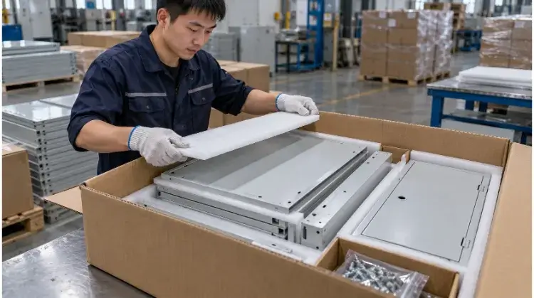
Packing Volume
Freight carriers charge based on dimensional weight (DIM weight). If you require the factory to fully weld and assemble a 2-meter-tall equipment rack before shipping, you are paying a premium to ship an empty box of air. Comparing the packed volume of a fully assembled unit against a “flat-pack” (knock-down) design often reveals massive savings in ocean freight or domestic trucking costs.
Beyond freight costs, shipping fully assembled frames significantly increases the risk of transit damage (e.g., bent chassis from forklift handling). Flat-packing inherently protects critical components better during global transit.
Connection Performance
When converting a welded frame to a flat-pack design, verify that the mechanical connections (such as heavy-duty bolts or structural blind rivets) still meet the required stiffness, load-bearing capacity, and IP-rating (sealing) for your application.
Assembly Costs
Flat-pack designs shift the assembly labor from the factory to the end-user or your local integration team. You must calculate the cost of local onsite labor, required hand tools, and final inspection to ensure the shipping savings outweigh the new local assembly costs.
Example Application:
Shipping 50 fully welded industrial cabinets from the factory might require two full shipping containers. Redesigning the cabinet as a bolted, flat-pack assembly might allow all 50 units to fit onto just four standard pallets. While this requires a slight increase in hardware costs and local assembly time, the reduction in global freight costs and transit damage risk usually results in a significantly lower Total Cost of Ownership (TCO).
Case Study: Performing a Cost-Reduction Review
Here is a recent real-world application (anonymized for NDA compliance) showing how TZR applied these DFM principles to a client’s industrial mounting base (Qty: 500, Material: Steel, Finish: Powder Coat).
- Original Design: Specified 3.0mm 304 Stainless Steel (despite indoor use), featured 3 different bend radii, utilized continuous seam welding for structural corners, and was shipped fully assembled.
- Modifications Applied:
- Material: Swapped to 2.0mm SPCC (Mild Steel) with added 15mm return flanges for rigidity.
- Bending: Unified all bends to a 2.0mm inside radius to match standard factory V-dies.
- Assembly: Replaced continuous welds with Tab & Slot self-locating features and stitch welds.
- Logistics: Shipped nested rather than fully assembled to reduce pallet volume.
- Resulting Cost Impact:
- Material costs dropped by 65%.
- Press brake setup time was reduced by 40%.
- Welding labor and fixture costs were reduced by 50%.
- Freight volume was reduced by 60%.
Ready to Optimize Your Fabrication Costs?
Before you send your next Request for Quote (RFQ), review your CAD models and drawings. Verify that your material choices, bend radii, hardware BOM, surface finishes, and tolerance requirements actually match the physical reality of the factory floor.
Not sure if your current design is driving up costs unnecessarily? Send your STEP files and PDF drawings to the TZR engineering team. We will run a comprehensive DFM analysis to identify your primary cost drivers and provide actionable, factory-tested redesign recommendations.