
 English
  Spanish
  German
  Russian
  Italian
  French
Centerless grinding is an outer-diameter (OD) machining process that removes material from cylindrical parts without using spindles or chucks. Instead, the workpiece is supported between a grinding wheel, a regulating wheel, and a workblade, enabling high-volume production with extreme dimensional precision.
Because there is no need to clamp and unclamp each individual part, this process drastically reduces setup and loading times. For engineers and purchasing managers, centerless grinding is the ultimate solution when standard CNC turning cannot meet tight OD tolerances or when machining long, slender shafts that would otherwise deflect under pressure.
Whether you are designing a new shaft or trying to reduce costs on an existing component, understanding the mechanics of centerless grinding is key. Here is a practical look at how the process works and what drives your manufacturing costs.
Process Quick Facts
- Target Objects: Cylindrical parts, straight pins, and stepped shafts (often handling length-to-diameter ratios up to 30:1 or more).
- Feed Methods: Through-feed, in-feed (plunge), and end-feed.
- Key Quality Metrics: OD tolerance (frequently held down to ±0.002 mm / ±0.0001″), cylindricity, and surface roughness (typically Ra 0.1 – 0.4 µm).
- Selection Criteria: High-volume production runs and strict OD requirements that conventional turning cannot reliably meet.
What Is Centerless Grinding and How Does It Work?
To understand how centerless grinding achieves precision without clamping the part, it helps to look at how the workpiece is supported and controlled during the grinding cycle.
Three-Point Support
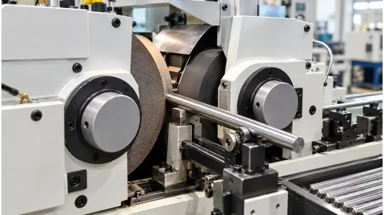
The stability of this process depends on a three-point support system. First, the grinding wheel performs the actual material removal. It rotates at high speeds and uses abrasive grains to cut the metal.
Opposite the grinding wheel is the regulating wheel, typically made of a rubber-bonded material. This wheel controls the rotation speed and feed rate of the workpiece.
Between them sits the work rest blade, which supports the workpiece from the bottom. Together, these three elements trap the part and keep it in continuous contact with the grinding zone.
Rotation and Feed
In centerless grinding, the workpiece is not driven by a motor or spindle. Instead, the friction from the regulating wheel causes the part to rotate against the grinding wheel.
Because the regulating wheel can be tilted at a slight angle, it also generates the axial force needed to push the workpiece through the machine.
By adjusting this tilt angle and the rotational speed, operators can control exactly how fast the part feeds. This setup directly determines both the final surface finish and the material removal rate.
Support and Setup
Eliminating chucks and centers reduces the loading time per part to near zero. This rapid cycle time is exactly what makes centerless grinding highly cost-effective at volume.
Additionally, the workpiece is supported along its entire length by the work blade. This minimizes the risk of deflection, which is a common problem when turning long, thin shafts between centers.
Shop-Floor Note: Because centerless grinding uses the existing outer diameter as its locating datum, it will grind a near-perfect cylinder, but it will not correct concentricity issues. If a part has an existing internal bore that is off-center from the rough OD, centerless grinding will not fix that runout.
Through-Feed vs. In-Feed vs. End-Feed Grinding
The physical shape of the part and the specific area that requires grinding dictate how the workpiece is fed into the machine. Centerless grinding uses three primary feed methods.
Through-Feed Grinding
In through-feed grinding, the workpiece enters one side of the machine, passes completely between the wheels, and exits the opposite side. The regulating wheel is tilted to pull the part through continuously, acting like a conveyor.
This method works well for straight, uniform cylindrical parts like dowel pins, roller bearings, and straight shafts. Because the part must travel entirely through the grinding zone, this process cannot be used for parts with shoulders, heads, or multiple diameters.
Expert Tip on Material: When quoting through-feed grinding, incoming bar stock straightness is critical. If the raw material has a significant bow, centerless grinding will simply grind a uniform diameter along that bowed path. We usually recommend a straightening operation prior to grinding for long shafts.
In-Feed Grinding
When a part has shoulders, multiple diameters, or complex profiles, it cannot pass straight through the machine. In these cases, in-feed (also known as plunge) grinding is used.
The workpiece is placed on the work blade against an end stop for precise positioning. The grinding wheel is then fed radially inward to grind the target area, and retracted so the part can be removed safely.
From a purchasing perspective, in-feed grinding involves higher setup costs. The grinding wheel must be custom-dressed to match the exact stepped profile of the part. This custom dressing extends setup time and requires specific tooling, which significantly drives up NRE costs for low-volume orders.
End-Feed Grinding
End-feed grinding is primarily used for parts with tapered profiles. The workpiece is fed axially into the grinding zone up to a designated stop, but it does not pass entirely through the machine.
Instead, the wheels are dressed to match the specific taper required by the print. Once the part reaches the end stop and the final dimension is met, it is withdrawn from the same side it entered.
Feed Methods Comparison
| Feed Method | Workpiece Movement | Typical Part Shapes | Grinding Zone & Limitations |
| Through-Feed | Continuous axial movement through the machine | Straight pins, dowels, rods, roller bearings | Grinds the entire OD. Cannot process parts with shoulders, heads, or multiple diameters. |
| In-Feed (Plunge) | Stationary axially; wheel feeds radially inward | Stepped shafts, valve spools, parts with flanges | Grinds targeted sections. Requires custom wheel dressing and individual loading; slower cycle time. |
| End-Feed | Fed axially to a stop, then retracted | Tapered pins, components with specific end profiles | Grinds up to a shoulder or stop. Limited to the width of the grinding wheel. |
When to Choose Centerless Over Other Processes
When evaluating manufacturing routes, engineers must decide whether centerless grinding adds necessary value or just unnecessary cost. The decision usually comes down to material hardness, geometric tolerances, and production volume.
Turning vs. Grinding
Modern CNC lathes can hold tight OD tolerances, often down to ±0.01 mm (±0.0004″). If your part is made of unhardened steel and requires standard fits, turning is usually sufficient and more cost-effective.
However, once a part undergoes heat treatment (e.g., reaching HRC 50 or higher), turning becomes highly inefficient. Centerless grinding is the go-to method for finishing hardened materials and hitting surface finishes that single-point turning simply cannot produce.
Furthermore, turning leaves a microscopic helical groove (lead) on the surface of the part. Under dynamic rotary seals, this groove acts like a pump and causes fluid leaks. Grinding provides a non-directional or cross-hatched surface, which is critical for shaft seal applications.
Centerless vs. Between-Centers
Between-centers (cylindrical) grinding holds the part using drilled center holes at each end. This method is excellent for guaranteeing strict concentricity across multiple stepped diameters, as everything is ground relative to a single, fixed centerline.
Centerless grinding eliminates the need for center holes, saving a dedicated machining step. However, because it relies on the part’s existing outer surface for support, it is best suited for parts where the primary requirement is OD size and roundness, rather than concentricity to an internal bore.
Combined Process Routes
Centerless grinding is frequently used as a material preparation phase before other machining steps. For example, Swiss-style CNC lathes rely on guide bushings that require highly consistent bar stock. Pre-grinding raw bar stock ensures it feeds smoothly, eliminating vibration and holding tighter tolerances on the turned features.
Another common route is the “Turn – Heat Treat – Grind” workflow. Parts are roughed out on a lathe while soft, leaving a small grinding allowance. After heat treatment warps the part, it is run through a centerless grinder to correct the thermal distortion and hit final print dimensions.
Engineering Case Study: Hydraulic Pump Drive Shaft
- Part Requirements: 4140 Steel shaft, case hardened to HRC 58. It features two bearing journals that require a ±0.002 mm tolerance and an Ra 0.2 µm finish.
- Candidate Routes: Hard turning vs. Between-centers grinding vs. In-feed centerless grinding.
- Selection Reason & ROI: Hard turning cannot reliably hold the Ra 0.2 µm finish without risk of seal leakage. Between-centers grinding would work, but requires center-drilling both ends—adding 15 seconds per part. Across a 10,000-unit run, skipping this single step by using in-feed centerless grinding saved over 40 hours of machine time, significantly lowering the final piece price.
What Accuracy and Finish Can You Expect?
When looking at a manufacturer’s capability list, it is easy to focus purely on the OD size tolerance. However, for a rotating component or a precision fit, size is only a fraction of the quality equation.
Diameter and Form
OD tolerance simply dictates the acceptable upper and lower limits of the diameter. However, a part can be perfectly within the OD tolerance but still fail in application if its form is incorrect.
Roundness ensures the part does not have high spots (lobes) that cause vibration in high-speed rotation. Straightness prevents the part from binding when inserted into a long, tight bore. Cylindricity combines roundness, straightness, and taper into a single 3D tolerance zone for critical sliding fits.
Datums and Runout
As mentioned earlier, a perfect OD does not guarantee perfect alignment with the rest of the part. Runout and concentricity specify how much a feature wobbles relative to a specific datum axis.
If an engineer designs a shaft and applies a tight runout tolerance between a centerless-ground OD and an internal threaded hole, the centerless process alone cannot control this relationship. The supplier must ensure the internal hole is machined perfectly true to the OD before grinding, or quote a completely different fixturing method.
Surface Roughness
Surface roughness (Ra) measures the microscopic peaks and valleys on the part’s surface. While centerless grinding can easily achieve an Ra of 0.1 µm (4 µin), requesting excessively low numbers drives up costs without always adding functional value.
A smoother surface requires finer grit wheels, slower feed rates, and longer “spark-out” times (letting the wheel run with no inward feed). An Ra of 0.4 µm is excellent for standard bearing fits. Pushing for 0.1 µm should be reserved for dynamic fluid seals where leakage is a major risk.
Shop-Floor Capability & Measurement Reference
| Metric | Typical Production Capability | High-Precision Limit | Standard Measurement Method |
| OD Size Tolerance | ±0.005 mm (±0.0002″) | ±0.0015 mm (±0.00006″) | Laser micrometer / Drop indicator |
| Roundness | 0.003 mm | 0.001 mm | Talyrond (Roundness tester) |
| Straightness | 0.01 mm per 100 mm | 0.002 mm per 100 mm | CMM / Optical comparator |
| Surface Finish (Ra) | 0.4 – 0.8 µm (16 – 32 µin) | 0.1 µm (4 µin) | Profilometer (Stylus trace) |
Note: The “High-Precision Limit” represents what is achievable under strictly controlled conditions (temperature-controlled coolant, continuous automated wheel dressing). Additionally, verifying a ±0.0015 mm tolerance requires temperature-controlled metrology labs and expensive inspection equipment (like laser micrometers), which adds significant Quality Assurance (QA) overhead to your final part cost.
How to Prepare Parts for Centerless Grinding?
The success of a centerless grinding operation is largely determined before the part ever reaches the machine. Incoming material state, dimensional allowances, and part geometry directly dictate how easily—and cost-effectively—a part can be ground.
Material and Hardness Impact
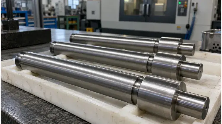
The material’s grade and its heat-treated state dictate the selection of the grinding wheel and the cooling strategy. Gummy materials, like unhardened 300-series stainless steel, tend to load up the grinding wheel quickly.
This requires the operator to pause the machine frequently to dress (clean and reshape) the wheel, driving up cycle times. Conversely, highly hardened alloys (HRC 60+) grind beautifully but may require expensive super-abrasive wheels (like CBN) to prevent rapid wheel breakdown.
Stock Allowance and Straightness
Grinding is a finishing operation, not a bulk material removal process. Leaving too much incoming stock forces the operator to run the part through the machine multiple times (roughing passes followed by a finishing pass), which multiplies the labor cost.
A standard grinding allowance should be around 0.1 mm to 0.2 mm (0.004″ to 0.008″) on the diameter. Furthermore, if a long shaft bows significantly during heat treatment, the grinder will not straighten it; it will simply grind a perfectly round OD along that bowed centerline.
Shoulders, Reliefs, and Interrupted Cuts
If your design requires grinding right up to a perpendicular shoulder, an undercut (relief groove) at the corner is mandatory. Without a relief groove, the sharp edge of the grinding wheel will break down rapidly, leaving an unground radius at the corner.
Features like cross-holes, keyways, or thin walls also pose extreme challenges.
DFM Warning on Thin-Walled Parts: Thin-walled tubing is particularly challenging for centerless grinding. The pressure between the regulating and grinding wheels can cause the tube to temporarily compress into an oval. Once it exits the machine and the pressure is released, the tube springs back, resulting in a part that is severely out of round and out of tolerance.
DFM & Incoming Material Assessment
| Design / Incoming Feature | What the Grinder Needs to Know | Potential Process Impact & Cost |
| Grinding near a shoulder | Is there a relief groove designed? | Without a relief, wheel corners break down, requiring constant wheel dressing and slowing production. |
| Incoming Stock Allowance | Is the allowance specified on the diameter or radius? | Excessive stock requires multiple passes. Too little stock means the part won’t “clean up” fully. |
| Long Shafts / Rods | What is the maximum allowable bow? | Severely bowed parts require a separate mechanical straightening operation before grinding. |
| Cross-holes or Keyways | Are the edges deburred before grinding? | Burrs can scratch the work blade. Large interruptions may require custom blade angles to prevent jumping. |
How to Inspect Parts and Troubleshoot Defects?
Quality assurance in grinding requires matching the right metrology tool to the specific print callout. When defects inevitably occur, knowing exactly what to look for separates experienced operators from novices.
Correlating Print Requirements to Inspection
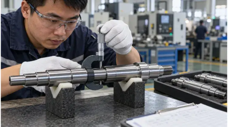
OD size is easily verified on the shop floor using standard micrometers or drop indicators. However, complex geometric forms like cylindricity require moving the part to a climate-controlled lab for CMM or Talyrond (roundness tester) inspection.
Surface integrity must also be evaluated carefully. Pushing feed rates too high can cause “grinding burn,” altering the microstructure of the metal beneath the surface. This is invisible to the naked eye and requires destructive testing or Nital etching to verify the heat treatment hasn’t been compromised.
Diagnosing Shop-Floor Defects
The most notorious centerless grinding defect is the “polygonal effect,” commonly yielding a three-lobed shape (a Reuleaux triangle). The OD measures perfectly with a standard micrometer, but the part will not fit into a precision precision-bored hole. This is strictly a geometric setup issue, fixed by adjusting the height of the work rest blade.
Chatter marks (visible parallel lines on the part) usually point to vibration. This could mean the grinding wheel is out of balance, or the regulating wheel has developed a flat spot. Taper issues (one end larger than the other) generally indicate a misalignment between the machine guides and the grinding zone.
Process Monitoring and SPC
Centerless grinding is highly stable once running, but wheel wear causes gradual dimensional drift. By measuring every 10th or 50th part, operators track the OD slowly growing as the wheel wears down, using Statistical Process Control (SPC) to stay ahead of the tolerance limit.
In advanced manufacturing setups, in-process laser gauges continuously monitor the exiting parts. This allows the CNC controls to automatically micro-step the wheel inward by a single micron without stopping production, ensuring zero defect drift over a massive production run.
Defect Troubleshooting Matrix
| Defect Manifestation | How to Confirm | Probable Cause | Primary First Adjustment |
| Lobing (Out-of-round) | V-block with dial indicator or roundness tester | Part center is set too low or too high relative to the wheels. | Adjust work rest blade height. |
| Chatter Marks | Visual inspection under light / Profilometer | Wheel imbalance or incorrect wheel dressing. | Re-true and dress the grinding wheel. |
| Tapering | Micrometer measurements at both ends | Guide plates misaligned with the regulating wheel. | Adjust entry/exit guide alignment. |
| Grinding Burn | Nital Etch test (surface turns dark) | Excessive stock removal rate or poor coolant flow. | Reduce feed rate; check coolant nozzles. |
What Drives Grinding Cost and Lead Time?
Pricing in centerless grinding is heavily weighted by the setup process and post-machining handling. Understanding how suppliers calculate total costs will help purchasing teams structure their RFQs to secure the best pricing.
Setup Time vs. Order Quantity
The physical setup for a centerless grinder—changing wheels, adjusting the blade height, setting the regulating wheel angle, dressing the wheel, and running first-article inspections—can take anywhere from 2 to 6 hours.
If you order 100 parts, that 4-hour setup cost is divided among very few units, making the piece price exorbitant.
Expert Tip on Purchasing: Never confuse EAU (Estimated Annual Usage) with Release Batch Size. If you quote an EAU of 12,000 parts but demand monthly shipments of 1,000, the supplier has to perform 12 separate setups. Your pricing will reflect the 1,000-piece batch, not the 12,000-piece volume.
Processing, Handling, and Packaging
Cycle time dictates the running cost. A part that requires 0.3 mm of stock removal might require two roughing passes and one finishing pass. By reducing the incoming stock to just 0.1 mm, you might eliminate the roughing passes entirely, cutting machine time by 60%.
Handling and logistics also add hidden costs. Highly finished parts (Ra 0.2 µm or better) require custom foam dunnage, individual netting, or rust-preventative oil to survive shipping. Bulk-shipping precision ground parts will inevitably cause surface scratching and part rejection, so packaging must be factored into the initial quote.
Ready to Optimize Your Precision Grinding?
Centerless grinding is a powerful process, but realizing its benefits requires tight alignment between your design, your incoming material, and your manufacturing partner.
Whether you are scaling up production on a critical aerospace fastener or troubleshooting concentricity issues on a hydraulic spool, we can help. Submit your drawings, incoming material state, and batch size requirements to our engineering team today, and we will provide a comprehensive process review and quotation tailored to your actual production goals.