
 English
  Spanish
  German
  Russian
  Italian
  French
The main difference between roughing and finishing in machining is their primary goal. Roughing removes bulk material quickly at high feed rates to create the basic shape. Finishing uses precise, shallow cuts to achieve the final dimensions, tight tolerances, and required surface roughness (Ra).
However, many engineers and machinists treat them simply as “fast” and “slow” speeds on a CNC machine. This leads to a costly misconception: assuming that a good finishing pass can fix a poorly roughed part. It cannot.
In this guide, we will break down the physical differences between roughing and finishing, explain how to determine the correct finishing allowance, and share actionable DFM strategies to help you reduce your CNC machining costs without sacrificing part quality.
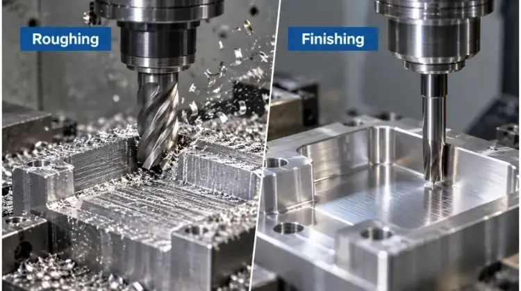
Roughing Vs. Finishing: What Changes in Machining
The transition from roughing to finishing involves a complete shift in machining strategy. It is not simply a matter of slowing the machine down.
Process Goals
Each stage optimizes for a different outcome. Roughing prioritizes stable, rapid bulk material removal to create the shape. Finishing focuses on hitting the final dimensional, geometric, and surface requirements to deliver the specification.
It is not as simple as “roughing is for speed and finishing is for quality.” Both stages require process stability, but they optimize for different physical results. Roughing requires rigid setups to prevent catastrophic tool failure, and finishing requires optimized toolpaths to control cycle times and prevent surface hardening.
Cutting Parameters
The physical interaction between the tool and the workpiece changes significantly between these stages. For typical aluminum components, roughing might leave a standard 0.3mm to 0.5mm stock on walls, but this shrinks to 0.1mm or less for micro-machining.
- Axial depth of cut and radial engagement: Roughing maximizes these to remove volume quickly. Finishing reduces them to minimize cutting pressure and tool deflection.
- Feed per tooth: Roughing maintains a high feed rate to evacuate chips and heat. Finishing lowers the feed rate to reduce scallop heights and achieve the specified Ra value.
- Cutting speed (RPM): Finishing usually involves lighter cuts, but it does not necessarily use slower spindle speeds. Speeds often increase during finishing to achieve a better surface finish, provided the tool and setup are stable.
- Stepover and toolpath tolerance: Finishing requires tighter toolpath calculations and smaller stepovers to prevent visible faceting on 3D contoured surfaces. Note on cost: Reducing the stepover for a smoother finish directly multiplies machine time, which pushes up the part price.
Tools and Quality
Using a finishing end mill for a roughing operation accelerates tool wear and increases tooling costs. Tools are engineered for specific loads.
| Factor | Roughing | Finishing |
| Main goal | Remove bulk stock | Reach final requirements |
| Material removal | High | Low and controlled |
| Tool priority | Strength and chip flow | Sharpness and accuracy |
| Cutting load | Heavy but stable | Light and consistent |
| Surface result | Intermediate tool marks | Specified final surface |
| Dimensional result | Near-net shape | Final size and geometry |
| Main risk | Heat, chatter and distortion | Size error and poor finish |
Engineering Note: These are common trends, not fixed rules. Machining 304 Stainless Steel requires a different approach than machining 6061 Aluminum, and factors like tool diameter, machine rigidity, and workpiece structure will shift the actual parameters.
Why Final Part Quality Starts With Roughing?
A common misconception in manufacturing is that surface finish and dimensional accuracy are determined entirely by the finishing tool. In practice, the conditions left by the roughing pass dictate whether the finishing pass succeeds or fails.
Toolpath and Chip Control
Modern CAM software provides various roughing strategies, each designed to control specific physical risks before finishing begins:
- Conventional roughing: Works well for simple, open profiles where tool engagement remains predictable.
- Adaptive clearing / Dynamic / Trochoidal milling: Controls the exact radial engagement of the tool. This prevents sudden overloads when the tool enters a corner, extending tool life and improving chip evacuation. This does not replace conventional roughing for all parts, but it is highly effective for deep pockets and hard materials.
- Rest machining: Uses a smaller tool to clear out material left in tight corners by the primary roughing tool. This stabilizes the remaining stock for the final pass.
Heat, Rigidity, and Thin Walls
Roughing generates significant forces and heat. If these are not managed, the part will distort. Common risks during the roughing stage include excessive tool overhang leading to chatter, weak workholding allowing the part to shift, and deep cavities trapping chips, which causes recutting and localized heat spikes.
For thin-walled components, the physical pressure of a heavy roughing cut can push the wall away from the tool, leaving unmapped excess material behind that the finishing tool is not expecting.
Pro Tip: Reducing feed may make the cut quieter, but it does not correct weak workholding, excessive tool overhang, or poor chip evacuation.
Uniform Remaining Stock
The most critical handoff between these two stages is the stock allowance. The finishing tool needs consistent stock, not simply more stock.
If roughing leaves 0.2mm of material on a flat wall, but 1.5mm of material bunched up in an internal corner, the finishing tool will experience a sudden spike in cutting load. This sudden load variation causes the tool to deflect, resulting in chatter marks, localized over-cutting, or worse, catastrophic tool breakage that destroys a near-finished part.
Case Study: Thin-Wall Deformation
Consider a thin-walled electronic housing machined from a 7075-T6 aluminum block. If the center cavity is entirely roughed out in one aggressive operation, the release of internal material stress combined with machining heat and clamping force will cause the walls to warp. The part may measure perfectly while clamped in the machine vise. However, the moment the clamps are released, spring-back occurs, often throwing flatness out of a tight 0.05mm tolerance.
In this scenario, modifying the finishing pass will not solve the problem. The roughing sequence must be changed—often requiring a roughing pass, a stress-relief pause (or unclamping and reclamping to a lower torque), and a semi-finishing pass before the final dimensions are cut.
How to Leave the Right Finishing Allowance?
There is no universal finishing allowance based simply on the material type. The correct amount of stock to leave depends heavily on the part’s specific features, the cutting tool diameter, and the rigidity of the setup.
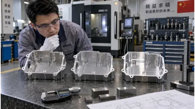
Allowance by Part Feature
Different geometries carry different machining risks. The allowance strategy must account for these variations:
| Feature | Main Risk | Allowance Priority |
| Flat face | Bowing and flatness errors | Even stock and solid underside support |
| Pocket wall | Tool deflection | Consistent side stock |
| Precision bore | Size and roundness | Controlled radial stock |
| Thin wall | Cutting pressure deformation | Light, balanced stock on both sides |
| 3D contour | Uneven remaining material | Constant surface stock (3D offset) |
| Turned diameter | Allowance confusion | Clearly state diameter or radial value |
When programming or reviewing a process, keep in mind that milling allowances are typically expressed per side. Turning allowances must be explicitly defined as either a diametrical or radial value to prevent scrap. Reference ranges provide a starting point, but they cannot replace a specific process evaluation based on the part’s size, tolerance, and material state.
Too Little Vs. Too Much
Getting the allowance wrong creates specific physical problems for the finishing tool.
Leaving too little stock may cause:
- Inability to clear the deep tool marks left by the roughing cutter.
- The tool rubbing instead of shearing, which leads to work hardening (especially in stainless steels and titanium).
- Insufficient material to correct a geometric error, such as a slightly tapered wall.
Leaving too much stock may cause:
- The finishing pass to act as a second roughing pass, accelerating tool wear.
- High cutting pressure that increases tool deflection, resulting in undersized dimensions.
- Thin walls to warp again under the heavy tool load. If this happens in the final pass, the entire machining investment up to that point is scrapped.
Semi-Finishing Decisions
Semi-finishing is an insurance policy. Skipping it to save 10 minutes of machine time on a high-value material is often a false economy.
The primary goal of semi-finishing is to level the remaining stock, not to achieve the final dimension. Adding a semi-finishing operation increases machine cycle time, but it becomes necessary when roughing leaves unpredictable material. It is usually required for deep pockets, mold cavities, complex 3D contours, internal corners with leftover material, hardened steels, or parts that exhibit noticeable distortion after bulk removal.
You can often skip semi-finishing for simple flat planes, open profiles, loose tolerances, or when the roughing pass naturally leaves a highly consistent allowance. For prototype runs, the extra CAM programming time for semi-finishing might occasionally cost more than the machine time it saves.
For highly precise or unstable parts, a standard operational sequence often looks like this:
Roughing → Cooling or Stress Relief → Re-Clamping (lower torque) → Semi-Finishing → Finishing
This is not a fixed rule for every component, but it is a reliable method for managing risk on high-value parts.
How Finishing Achieves Tolerance and Surface Quality?
A successful finishing pass converts the prepared blank into a component that passes inspection. This requires specific tooling, controlled parameters, and an understanding of how dimensions interact with subsequent manufacturing steps.
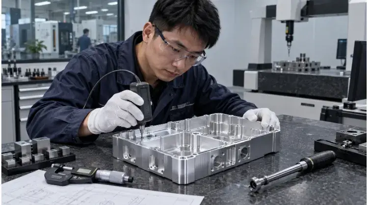
Finishing Tools and Toolpaths
Tool selection must match the feature requirements. Machinists use flat end mills for vertical walls and flat floors, ball nose cutters for 3D contoured surfaces, wiper inserts for smooth turned diameters, and reamers or fine boring heads for precision holes.
A finishing tool must be sharp, in stable condition, and held in a holder with minimal runout. The tool overhang should be kept as short as possible to prevent vibration.
This is also where design choices directly impact cost. Standardizing internal corner radii on your CAD model reduces machining time. If you design an internal corner that requires a custom or ultra-fragile micro-end mill to clear out, your part price will multiply simply because of tool changes and slower feed rates.
Additionally, a common mistake is assuming that lowering the feed rate always improves the surface finish. While smaller stepovers and lower feeds generally reduce scallop height, lowering the feed rate too much prevents the cutting edge from engaging the material. Instead of cutting, the tool rubs, generating excess heat, wearing out the edge prematurely, and smearing the surface.
Dimensions, Geometry, and Ra
It is important to differentiate between dimensional tolerance (the physical size), geometric tolerance (shape, orientation, and position), and surface roughness (the microscopic texture, often measured as Ra).
A part can meet its Ra requirement and still fail flatness, roundness, position, or sealing performance.
| Feature | Main Requirement |
| Bearing seat | Tight size control and roundness |
| Sealing face | Flatness and specific surface lay/direction |
| Precision bore | Diameter, true position, and cylindricity |
| Mating surface | Size, flatness, and orientation |
| Cosmetic face | Consistent, visually appealing tool marks |
| Hidden cavity | Functional clearance only |
Inspection and Coating Allowance
Process control during the finishing stage separates reliable suppliers from inconsistent ones. Before taking the final cut, a machinist will verify the remaining stock, check the datums, apply tool wear compensation offsets, and ensure the machine and workpiece have stabilized in temperature. Critical dimensions are always checked before the part is removed from the fixture, as reclamping a finished part for rework is difficult and risks surface damage.
If the part requires a secondary surface treatment, the machining dimensions must account for it. Anodizing, plating, and powder coating all alter the final fit.
Furthermore, nominal coating thickness does not equal the total dimensional change. For example, standard anodizing penetrates the aluminum and builds up on the surface, meaning a 10 µm coating only adds about 5 µm to the part’s radius.
A 50 µm hard anodizing requirement does not automatically mean every machined dimension should be offset by 50 µm. Confirm the coating buildup, growth direction, masking plan, and final inspection condition first.
DFM Rule: Always explicitly state “Dimensions apply AFTER coating” or “Dimensions apply BEFORE coating” in the drawing notes to avoid supplier guesswork.
How to Reduce Machining Cost Without Added Risk?
Over-specification is one of the most common reasons for inflated machining quotes. Engineers often apply tight tolerances and flawless surface finishes across an entire part out of caution.
Real Cost Drivers
To cut costs without sacrificing part performance, you need to know exactly what you are paying for in each stage of the process.
Roughing costs are typically driven by:
- Total volume of material removed.
- Heavy machine runtime and power consumption.
- Rapid tool wear (especially in tough materials).
- Chip evacuation and coolant management.
- Heavy-duty fixturing required to hold the raw block under high cutting loads.
Finishing costs are typically driven by:
- Longer toolpaths resulting from tiny stepovers.
- Specialized or custom tooling (like micro-end mills or form tools).
- Machine pauses for operators to check dimensions and apply tool wear offsets.
- Process measurement and final CMM inspection.
- The high risk of scrap (a mistake here wastes all the sunk cost of the roughing stage).
Avoid the generic assumption that “roughing takes 30% of the time and finishing takes 70%.” Costs vary wildly based on the material and geometry. For example, when machining a complex aerospace bracket from Ti-6Al-4V, roughing will burn through expensive carbide inserts rapidly. However, the finishing stage will still dominate the final invoice due to the hours of microscopic stepovers required to avoid work-hardening the titanium, followed by mandatory CMM inspection for true position tolerances.
DFM Changes
The most effective way to lower your quote is to remove machining requirements that offer no functional value. Here are actionable Design for Manufacturing (DFM) adjustments:
- Stop using blanket Ra values: Do not demand an Ra 0.8 (32 µin) finish across the entire part. Reserve it for bearing seats, O-ring grooves, or sliding surfaces. Allowing non-contact faces to remain at a standard Ra 3.2 (125 µin) can cut finishing cycle times by 30% or more.
- Isolate tight tolerances: Only specify strict dimensional or geometric tolerances on functional mating surfaces.
- Standardize internal corners: Match internal corner radii to standard end mill sizes, and ideally, make the radius slightly larger than the tool so it can sweep through the corner without chattering.
- Avoid deep, narrow pockets: Reaching into deep cavities (anything exceeding a 4:1 length-to-diameter ratio) requires long, fragile tools. This forces the machinist to drop the feed rate dramatically to prevent vibration during both roughing and finishing.
- Clarify cosmetics: Clearly denote which surfaces are cosmetic and which will be hidden inside an assembly.
- Accept normal tool marks: Allow uniform machining marks on non-critical surfaces instead of requiring a seamless, polished look.
Procurement Tip: A tighter tolerance should solve a functional problem. If it does not affect fit, motion, sealing, or service life, it may only increase machining and inspection cost.
Conclusion
Roughing creates the conditions for the final cut. Finishing converts those conditions into the dimensions, geometry, and surface required by the drawing. The best machining plan connects both stages through controlled stock, stable workholding, suitable tooling, and realistic specifications.
Send your 2D drawings and 3D models to the TZR engineering team for a free DFM review. We will identify risky tolerances, uneven stock conditions, thin-wall issues, and possible cost-saving changes before your production begins.
FAQs
Can I use one tool for both roughing and finishing?
Using the same tool for both operations is poor practice for precision metal machining. Roughing subjects the cutting edge to high heat and impact, causing micro-wear. If you use that dulled edge for finishing, the tool will push the material rather than shear it. This causes severe tool deflection, meaning the machine cuts less material than programmed, resulting in tapered walls and failed tolerances.
What is a typical finishing allowance?
For general aluminum or steel components, a standard milling allowance is typically between 0.2mm and 0.5mm per side. However, this shrinks to 0.1mm or less for micro-machining and can exceed 1.0mm for large castings. The exact allowance always depends on the tool diameter, part rigidity, and depth of cut.
Is semi-finishing required for simple parts?
No. If the part features open profiles, loose tolerances, and is rigid enough to resist warping, you can skip semi-finishing. As long as the roughing pass leaves a consistent, thin layer of stock, the finishing tool can proceed directly without issue.
How do surface treatments affect the finishing pass?
Treatments like hard anodizing, nickel plating, or powder coating add material thickness. The machinist must intentionally machine the part oversized (for internal features like bores) or undersized (for external features like shafts) during the finishing pass so that the part hits the required tolerance after the coating is applied.
What drives the main costs in roughing vs. finishing?
Roughing costs are primarily driven by the sheer volume of material removed, spindle power, and rapid insert wear. Finishing costs are driven by extended machine cycle times (due to very small stepovers and low feed rates) and the hidden costs of quality control, such as CMM measurement and the extreme financial risk of scrapping a nearly completed part.