
 English
 Spanish
 German
 Russian
 Italian
 French

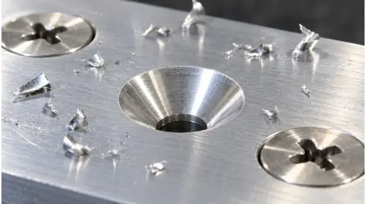
A countersink hole is a conical recess machined at the top of a pilot hole, allowing a flat-head fastener to sit flush with the part’s surface. Standard countersink angles are 82° for ANSI (Imperial) and 90° for ISO (Metric) fasteners.
When a screw head protrudes above the surface, a shallow hole is not always the only cause. The countersink angle, fastener dimensions, seating surface quality, and applied surface treatments all dictate the final fit. Discovering a protruding screw on the assembly line often leads to costly rework or scrapped parts. This guide explains how to determine dimensions, evaluate part structure, and verify the finished feature for assembly.
Quick Verification Checklist
Before releasing a drawing or starting a machining setup, confirm these five elements:
| Check Item | Primary Elements to Confirm |
| Fastener | Manufacturing standard (ISO/ANSI), head style, and maximum head dimensions. |
| Geometry | Pilot hole diameter, countersink major diameter, and exact included angle. |
| Part Structure | Remaining material thickness, edge distance, and proximity to bends. |
| Surface Finish | Coating thickness allowance and whether the seating surface requires masking. |
| Inspection | Measurement method (gage vs. caliper) and physical fit-check requirements. |
Choose the Right Hole for Your Fastener
Selecting the correct hole profile ensures joint stability and a clean finish. Understand when a countersink is required and when a counterbore provides better structural support.
Geometry and Function
A standard countersink consists of a cylindrical pilot hole and a conical seating surface. The tapered geometry allows a flat-head fastener to wedge into the recess, which centers the screw and pulls the mating parts together.
It is necessary to distinguish a functional countersink from a standard deburring chamfer. A chamfer simply breaks a sharp edge. A countersink is precisely angled and sized to support a specific mechanical load. Flush installation is typically used for outer panels, aerodynamic covers, and assemblies where protruding fastener heads would interfere with moving parts.
Compatible Fasteners
Countersink holes work specifically with fasteners that feature a matching conical profile, such as flat-head screws and countersunk rivets.
When specifying the hole, the head shape is the determining factor, not the drive type. Hex, Phillips, and Torx are drive styles; they can all be manufactured with flat heads. It is also important to differentiate between standard flat-head screws, which require a completely flush surface, and oval-head (raised countersunk) screws, which have a domed top for aesthetic purposes but still rely on the exact same conical seating surface below.
Countersink vs Counterbore
While a countersink uses a conical seat for flat-head fasteners, a counterbore uses a flat-bottomed cylindrical recess for socket-head cap screws. The selection depends on the fastener type, available material thickness, and structural requirements.
A countersink transfers clamping force along an angled face, creating radial stress. This radial stress can distort thin sheets or cause cracking in softer materials like aluminum and acrylic. A counterbore transfers the load vertically down a flat surface, offering better load distribution for rigid clamping.
| Hole Type | Compatible Head | Primary Use | Design Limitations |
| Countersink | Flat-head, Oval-head, Countersunk rivets | Flush surfaces, panels, aerodynamic skins | Radial stress can distort thin materials; requires precise angle matching. |
| Counterbore | Socket head cap, Hex bolts | Heavy load bearing, structural joints, rigid clamping | Requires more material thickness; flat bottom machining requires tool clearance. |
Set Dimensions, Tolerances, and Drawing Callouts
Accurate dimensions and clear drawings prevent mismatched hardware and assembly failures. Learn how to specify angles, calculate depth, and properly call out countersinks for manufacturing.
Angle and Major Diameter
The dimensions of a countersink must match the standard of the chosen fastener. Minor angle mismatches result in line contact rather than surface contact, which causes uneven loading and eventual loosening.
The two most common standard angles are 90° for metric (ISO) fasteners and 82° for imperial (ANSI) fasteners. Aerospace fasteners often require 100° angles to distribute loads across thinner sheet metals.
When defining the dimensions, clearly separate the pilot hole diameter (which accommodates the screw thread or shank), the fastener’s maximum head diameter, and the countersink’s major diameter. The major diameter is typically specified slightly larger than the screw head to ensure the fastener sits completely flush.
Pro Tip: Tolerance Stack-up
Fastener heads are manufactured with their own tolerances based on Maximum Material Condition. An overly tight major diameter on the drawing might work perfectly for one batch of screws, but cause the next batch to protrude. Always leave a reasonable tolerance buffer for the major diameter.
Typical Reference Dimensions:
| Fastener Standard | Example Thread | Pilot Hole (Normal Fit) | Countersink Major Diameter | Countersink Angle |
| ISO Metric | M4 | 4.5 mm | 9.18 mm | 90° |
| ANSI Inch | #8 | 0.177 in | 0.385 in | 82° |
Depth and Flushness
The geometric depth of a countersink is not a directly machined parameter; it is the mathematical result of the major diameter, pilot hole diameter, and included angle. Machinists control the depth by feeding an angled cutter until the correct major diameter is achieved.
The depth $h$ can be calculated using the following formula:
h = (D – d) / [2 tan(θ/2)]
Where:
- D = Countersink major diameter
- d = Pilot hole diameter
- θ = Included countersink angle
A nominal calculation provides the baseline geometric depth, but actual flushness depends on the tolerance ranges of the machined features and the surface finish.
Shop Floor Reality: Coating Allowances
The nominal calculation above is for bare metal. If the part requires anodizing or powder coating, the coating thickness will reduce the effective major diameter and the pilot hole size, pushing the screw upwards. To prevent assembly issues, the major diameter must be machined slightly larger to account for the coating thickness.
Complete Drawing Callouts
A proper drawing callout leaves no ambiguity for the machinist. It must define the pilot hole diameter, the countersink major diameter, and the included angle.
The standard symbol for a countersink is ⌵. A complete callout specifies the exact features, for example: ⌵ Ø 10.5 × 90°.
The drawing should also indicate whether the required flushness applies to the bare machined part or the final coated part. If positional accuracy is critical for assembly, apply standard Geometric Dimensioning and Tolerancing (GD&T) controls, such as True Position, to the pilot hole. The countersink inherently shares the same datum axis as the pilot hole.
Machinist Note: The Default Angle Trap
Never leave the countersink angle to assumption. If an angle is omitted on a drawing, a US-based shop will generally default to 82°, while a European or Asian shop may default to 90°. This single omission is a leading cause of mismatched hardware and rejected parts.
Check Thickness, Edge Distance, and Bend Clearance
A perfectly dimensioned countersink fails if the surrounding material cannot support it. Review material thickness and part geometry early to prevent structural weakness, edge bulging, and manufacturing interference.
Remaining Thickness
The most common structural failure with countersinks occurs when they are applied to sheet metal that is too thin. You must compare the calculated geometric depth of the countersink against the actual material thickness.
If the countersink depth consumes too much of the material, it leaves a razor-thin edge at the bottom of the pilot hole. When torque is applied during assembly, the radial stress from the fastener head will distort this remaining material or pull the screw entirely through the sheet. As a general manufacturing guideline for load-bearing joints, the depth of the countersink should not exceed 60% of the material’s total thickness.
Edge and Bend Clearance
Countersink major diameters are significantly larger than their pilot holes, requiring ample clearance from edges and bends.
Placing a countersink too close to a part’s edge increases the risk of the material tearing or bulging outward during fastener installation. Furthermore, placing a countersink too close to a bend line creates tooling interference: the angled cutter will strike the vertical flange, damaging both the tool and the workpiece. Always calculate clearance from the major diameter of the countersink, not the center point of the pilot hole.
Shop Floor Reality: The 1.5x Rule
As a standard rule of thumb, the minimum distance from the edge of the part to the center of the countersink should be at least 1.5 times the major diameter. This provides enough surrounding material to safely absorb the radial expansion forces without edge deformation.
Cut vs Formed Countersinks
When the sheet material is too thin to safely machine a countersink, punching (forming) the feature is often the required alternative in sheet metal fabrication.
Machining (cutting) removes material to create the cone, leaving a flat back side. Forming physically stamps the sheet metal, displacing material downward to create a dimple that matches the fastener head. While forming requires a clearance hole on the mating part to accept this protruding dimple, the stamping process induces work hardening around the hole. This actually makes the formed joint stronger and more resistant to pull-through than a machined countersink in thin sheet metal.
| Feature Type | Material Alteration | Back Side Result | Mating Part Requirement | Best Use Case |
| Cut (Machined) | Material removed | Flat | Standard tapped hole or nut | Thick plates, CNC machined parts, castings |
| Formed (Stamped) | Material displaced (Work hardened) | Protruding dimple | Clearance hole required to accept dimple | Thin sheet metal, high-volume stamping |
Control Machining Defects and Coating Effects
Consistent machining and precise coating allowances dictate the final fit. Address tooling setup and surface finishes proactively to maintain tight dimensional control across production batches.
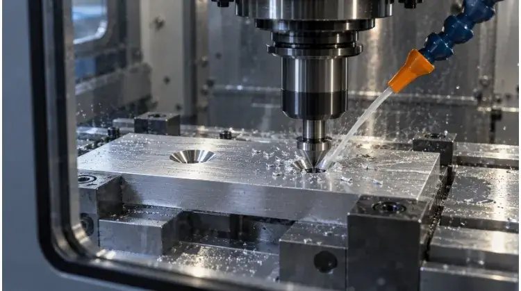
Tooling and Setup
Achieving a clean, concentric countersink requires proper tooling alignment and rigidity. A countersink must share the exact same center axis as the pilot hole; any misalignment results in an eccentric seating surface that prevents the fastener head from sitting flat.
Tool selection depends heavily on the material and setup rigidity. Multi-flute cutters are standard for harder alloys but are prone to chatter in softer materials. If surface finish issues arise in aluminum or plastics, consider switching to a zero-flute (cross-hole) countersink. The cutting geometry of a zero-flute tool naturally prevents chatter and ejects chips efficiently. Additionally, for thin sheet materials, provide physical support directly underneath the hole during machining to prevent the downward pressure of the Z-axis from deflecting the part.
Machining Troubleshooting
When defects occur on the shop floor, methodical troubleshooting is required. Use this sequence to identify and correct common countersinking issues before adjusting part design:
| Defect | Primary Check | Adjustment Direction |
| Surface Chatter (Vibration marks) | Tool rigidity, flute count, and cutting parameters | Decrease spindle speed. Ensure the workpiece is firmly clamped. Switch to a zero-flute cutter if machining soft metals. |
| Burrs at Hole Edge | Tool sharpness, material condition, and feed rate | Replace worn tooling. Optimize feed rates to cut rather than push the material. Implement a controlled deburring pass. |
| Eccentric Countersink (Off-center) | Spindle alignment, part fixturing, and setup shifts | Verify the spindle aligns perfectly with the pilot hole datum. Check for part movement during tool changes. |
| Inconsistent Major Diameter | Tool wear, Z-axis offset, and measurement methods | Monitor tool wear and adjust Z-axis depth compensation. Ensure chips are not accumulating under the depth stop. |
| Sheet Deflection (Part bending) | Downward cutting force and underlying support | Reduce Z-axis feed pressure. Add physical support blocks directly beneath the hole during the machining cycle. |
Coating Allowances
Surface treatments change the dimensions of a machined hole, and countersinks are particularly sensitive to these changes because the angled surface amplifies the effect on flushness.
When a part undergoes anodizing, powder coating, or painting, the coating builds up on the conical seating surface. This buildup decreases the effective major diameter and pushes the fastener head outward. The required machining allowance depends entirely on the coating type: a Type II anodize may only add 0.0005 inches of buildup, requiring minimal adjustment, while a powder coat can add 0.003 to 0.005 inches, which will severely impact flushness. Calculate the expected coating thickness and machine the countersink slightly deeper to compensate, verifying the fit on a finished first-article part.
Shop Floor Reality: Masking Challenges
Do not simply add a “mask hole” note to the drawing to solve coating buildup. Standard silicone masking plugs do not seal well inside conical countersinks, leading to paint bleed and increased manual labor costs. It is highly recommended and more cost-effective to oversize the machined countersink major diameter than to pay for custom masking labor.
Inspect Finished Holes and Evaluate Assembly Problems
Verifying the final countersink prevents assembly line delays and ensures joint integrity. Learn how to inspect dimensions, perform functional fit checks, and evaluate formal rework options.
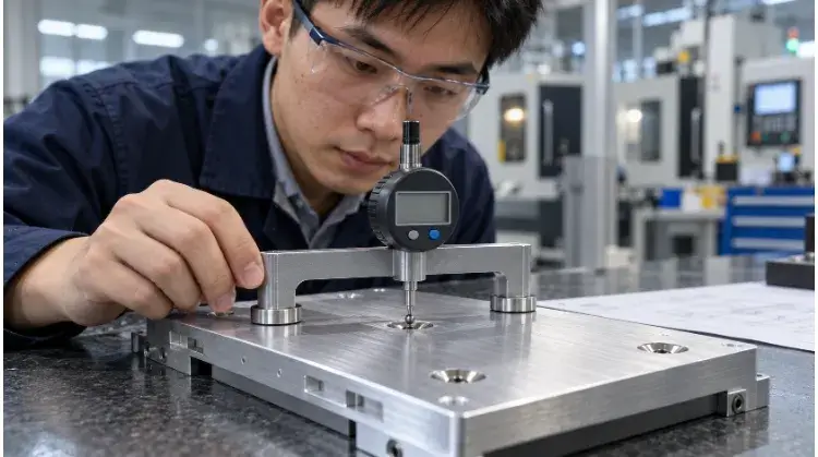
Dimensional Inspection
Visual inspection is insufficient for verifying countersink geometry. Because the transition from the surface to the conical taper often contains a microscopic radius or burr, using standard calipers to measure the major diameter typically yields inaccurate results.
Customer-supplier disputes frequently occur when incoming quality control (IQC) uses calipers while the machine shop uses a dedicated countersink drop gage. Always align on the exact measurement method before production begins. For tight tolerances, precision requires a Coordinate Measuring Machine (CMM) or an optical profile projector to verify the exact included angle, concentricity with the pilot hole, and surface profile.
| Check Item | Measurement Method | Acceptance Criteria | Record Requirement |
| Major Diameter | Countersink gage or CMM | Within specified tolerance band | Gage reading or CMM report |
| Included Angle | CMM or optical comparator | Matches drawing specification (e.g., 90° ±1°) | First-article verification |
| Concentricity | CMM or pin gage setup | Shares datum axis with pilot hole | Position tolerance data |
| Seating Surface | Visual or profilometer | Free of chatter marks, burrs, and steps | Pass/Fail |
Assembly Verification
Dimensional compliance does not guarantee a successful assembly if the physical fasteners deviate from their nominal dimensions. A functional fit check using the actual specified fastener is a mandatory final step.
Insert the designated fastener and apply the production torque. A fastener inserted by hand will sit differently than one driven to its final torque specification. Torque causes radial expansion and material settling, which can turn a seemingly flush screw into a protruding one. Inspect the seating contact; the head should sit uniformly without unilateral tilting, which indicates an angle mismatch or an off-center cut. Record dimensional inspection and functional fit checks separately—a screw simply “fitting into the hole” does not override geometric tolerance requirements.
Rework Decisions
When a countersink fails inspection, the rework path depends on whether the feature is under-cut (screw protrudes) or over-cut (screw sits too deep).
For a protruding fastener, investigate the root cause—such as missed burrs, excessive coating buildup, or mismatched fastener angles—before returning the part to the machine. Re-machining an under-cut countersink is feasible but requires precise re-fixturing to avoid cutting an off-center double taper.
Over-cut countersinks present a severe structural issue because material cannot be added back. While swapping to a larger fastener or inserting a countersink washer might physically salvage the part, these are structural design changes. They require formal Material Review Board (MRB) approval or a signed deviation request from the engineering team before implementation. Never treat unapproved part modification as a default manufacturing remedy.
Fastener and Countersink RFQ Checklist
To ensure accurate pricing and DFM feedback for sheet metal fabrication or CNC machining, include the following details when requesting a manufacturing quote:
| Submission Item | Required Information |
| Drawings & Models | Current revision, specific countersink locations, and machining direction. |
| Material & Volume | Alloy grade, actual sheet thickness, and expected production batch size. |
| Fasteners | Exact manufacturing standard (e.g., ISO, DIN, ANSI), thread size, and head style. |
| Surface Finish | Specific coating type, and whether the seating surface requires coverage or masking. |
| Inspection Criteria | Dimensional tolerances, acceptable flushness limits, and physical fit-check requirements. |
Pro Tip for Procurement:
If aesthetic flushness is critical to your product, do not rely on standard dimensional callouts alone. Ship a handful of the actual physical fasteners to your manufacturing partner for first-article fit checks. Fastener batch variances are the hidden variables no engineering drawing can account for.
Ready for Production? Submit your 3D models, 2D drawings, and fastener specifications to our platform. Our engineering team will review your countersink dimensions, verify material thickness limits, and ensure your custom parts are optimized for a flawless final assembly.