
 English
 Spanish
 German
 Russian
 Italian
 French

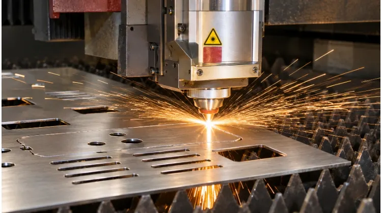
The best method for cutting stainless steel depends on thickness and heat tolerance. Fiber lasers are optimal for thin sheets up to 20mm, plasma for heavy structural plates, waterjets for heat-sensitive parts requiring zero HAZ, and bandsawing for solid bar stock. Proper selection prevents work hardening and thermal distortion.
Cutting stainless steel introduces unique challenges not found in mild steel. Because austenitic grades (like 304 and 316L) have high tensile strength and poor thermal conductivity, they are highly susceptible to work hardening during mechanical cutting and localized warping during thermal cutting.
Based on our shop floor experience at TZR, this guide breaks down how to match the right cutting technology to your part geometry, how to avoid common defects, and how to write clear RFQ specifications that guarantee assembly-ready parts.
Use the baseline matrix below to determine the most cost-effective routing for your material format and primary constraints.
| Cutting Method | Best Suited For | Typical Thickness | Key Consideration | Relative Cost |
| Fiber Laser | Sheet profiles, tight tolerances | 0.5mm – 20mm | Requires high-pressure N2 gas to prevent edge oxidation. | $$ |
| Plasma | Heavy plates, large structures | 15mm – 50mm+ | Leaves a wider Heat-Affected Zone (HAZ) and dross. | $ |
| Abrasive Waterjet | Thick plates, heat-sensitive parts | 1mm – 100mm+ | Zero HAZ, but requires taper compensation. Slower speed. | $$$ |
| Bandsaw | Bar stock, thick-walled tubes | N/A (Solid stock) | Must control feed rate to prevent work hardening. | $ |
| Shearing | Straight cuts on thin sheets | 1mm – 6mm | Induces mechanical stress; leaves a sharp burr. | $ |
Choose the Right Stainless Steel Cutting Method
Selecting the right process means matching equipment limits to your part’s geometry. At TZR, we review print tolerances against actual production capabilities before determining the routing.
Laser and Plasma
Thermal cutting is the standard for sheet and plate profiling.
Fiber laser cutting works best for intricate contours, sharp internal corners, and tight tolerances (typically ±0.1mm). When cutting stainless steel, we use nitrogen (N2) as the assist gas—typically requiring 15–20 bar of pressure for thick plates—to blast away molten material and leave a clean, oxide-free edge. When evaluating suppliers, always differentiate between a laser’s maximum piercing capacity and its stable production capacity. Pushing a machine to its absolute limit usually results in edge blowouts and high scrap rates.
Plasma cutting becomes the practical choice for thicker plates (above 15mm) where laser speeds drop significantly. While plasma is faster and cheaper for heavy plates, it introduces intense heat. This creates a wider Heat-Affected Zone (HAZ), a slight edge bevel, and bottom dross (slag) that requires secondary grinding before welding.
Abrasive Waterjet
Abrasive waterjet is a non-thermal process used when controlling heat input is non-negotiable.
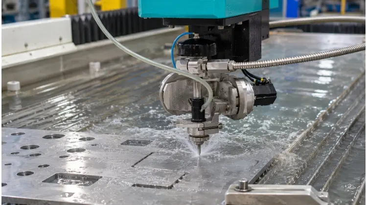
Because it operates cold, waterjet cutting eliminates the HAZ, ensuring the material retains its original metallurgical properties. However, you must account for kerf taper (a V-shaped edge profile) and visible edge striations. Modern equipment mitigates this using 5-axis cutting heads for active taper compensation, but this slows the cutting speed. We do not use waterjet for thin sheets unless absolutely necessary, as the high garnet abrasive consumption and slow speeds drive up the per-part cost significantly.
Sawing and Shearing
Mechanical methods are used for straight separation, not profiling.
Bandsawing is the go-to for cutting solid stainless bar stock and structural tubing to length. The primary limitation is clamping; secure workholding is required and can sometimes mark the material surface. Shearing provides rapid, straight-line cuts on sheet metal but applies severe shearing force. This induces mechanical stress, roll-over, and a sharp burr.
Note on Tube Profiling & Field Tools: For complex hole patterns on tubular stock, CNC tube lasers are the industrial standard. Hand tools like angle grinders and portable saws are strictly for field modifications and are not used in precision manufacturing routings.
Process Comparison Matrix
| Process | Applicable Forms | Contour Capability | Heat Effect (HAZ) | Edge Condition | Typical Post-Processing |
| Laser (N2) | Sheet, Plate, Tube | High (complex, small holes) | Minimal (narrow) | Clean, smooth | Light deburring if required |
| Plasma | Plate | Moderate (simple shapes) | High (wide) | Rougher, dross present | Grinding, dross removal |
| Waterjet | Sheet, Plate | High | None | Matte, striations | Edge breaking |
| Sawing | Bar, Tube | None (straight only) | None | Tool marks | Deburring, facing |
| Shearing | Sheet | None (straight only) | None | Roll-over, burr | Edge rounding, deburring |
Control Heat, Hardening, and Cutting Defects
Defects in stainless steel cutting usually stem from poor thermal management or mechanical friction. Identifying the root cause determines whether you need to adjust machine parameters or add a secondary operation.
Work Hardening
Austenitic stainless steels are highly prone to work hardening during mechanical cutting (sawing, drilling, milling). Note that grade 316L is even more susceptible to work hardening than 304 due to its higher nickel and molybdenum content.
If a tool rubs against the material without digging in to remove a chip, friction generates heat and hardens the surface layer instantly. To prevent this, the cutting tool must maintain a constant, aggressive feed rate to stay beneath the hardened layer. Letting a saw blade idle in the cut will destroy the tool in seconds. Work hardening is strictly a mechanical machining issue and does not apply to non-contact methods like laser or waterjet.
Heat and Distortion
In thermal cutting, you must control the HAZ, heat tint (oxidation colors), and overall part distortion.
Distortion is a severe risk in thin sheets, long asymmetrical parts, or areas with dense hole patterns. When localized heat builds up, the stainless steel expands and warps. Warped parts often fail to seat correctly in CNC press brake backgauges or robotic welding fixtures, increasing manual setup time and scrap rates downstream. We control this at the programming level by adjusting the cutting sequence—piercing non-adjacent features to let heat dissipate—and managing sheet support on the machine bed.
Burrs and Cut Drift
Different processes produce specific edge defects. If your drawing calls out strict edge states (e.g., ISO 13715 for undefined shape edges) or specific surface roughness (Ra), you must align the defect management plan with the chosen process:
- Mechanical Burrs: Occur in shearing and sawing when the material tears at the exit point. Requires mechanical deburring or edge rounding.
- Dross (Slag): Occurs in laser and plasma cutting when molten steel solidifies on the bottom edge. Hard dross in laser cutting usually points to incorrect nitrogen pressure, poor nozzle condition, or wrong focal position.
- Cut Drift: Happens in bandsawing when blade tension is too low or the feed rate is too high, resulting in an angled cut on thick bar stock.
Defect Troubleshooting Guide
| Defect Type | Probable Causes | Check Direction / Parameter Adjustments | Applicable Process |
| Severe Work Hardening | Tool rubbing, low feed rate | Increase feed rate; ensure constant chip load and high coolant flow. | Sawing, Machining |
| Warping / Distortion | Localized heat buildup | Optimize cut sequence; allow heat dissipation; check slat support. | Laser, Plasma |
| Hard Bottom Dross | Incorrect gas pressure, slow speed | Increase N2 pressure, clean nozzle, adjust focus position. | Laser, Plasma |
| Angled Cut (Drift) | Blade deflection, excessive feed | Check blade tension, reduce feed rate, verify clamp rigidity. | Bandsaw |
| Heavy Edge Striations | Cutting speed too high | Reduce travel speed; check abrasive flow rate. | Waterjet |
Define Dimensions, Edges, and Surface Requirements
Vague drawing notes like “smooth edges” or “clean finish” force suppliers to guess your intent. This usually leads to one of two outcomes: the supplier over-processes the part and inflates your quote, or they under-process it, leaving you with parts that fail in assembly. To get accurate pricing and usable components, you must translate quality expectations into executable manufacturing instructions.
Dimensions and Flatness
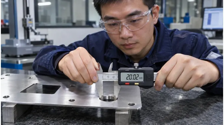
Do not assume all dimensions on a profile will be met by the cutting machine alone. You need to distinguish between outer profile dimensions, hole sizes, positional accuracy, and flatness.
Identify which features are critical for your assembly. Tighter tolerances do not scale linearly in cost—they scale exponentially. Specifying a ±0.1mm tolerance on a laser-cut profile is standard and incurs no extra fee. Tightening that to ±0.05mm forces the part onto a CNC mill, instantly tripling the cycle time and setup cost. Furthermore, state your flatness requirements and measurement datum. Cutting relieves internal stresses in stainless steel, which can cause the material to bow. If strict flatness is required, state it clearly so the supplier can route the part for secondary leveling.
Edge Condition
Different downstream processes demand different edge states. Instead of asking for a “smooth edge,” specify exactly what the shop floor needs to do.
Differentiate between standard deburring (removing the sharp mechanical burr or dross), chamfering (cutting a specific angle for weld prep), and edge rounding. If the part will be powder coated or painted, you must call out edge rounding. Surface tension causes liquid paint and powder coats to pull away from sharp 90-degree edges, leaving them exposed. A part that looks perfect out of the box will start rusting at the edges within months in the field. Reference specific standards like ISO 13715 or call out a measurable edge radius.
Surface Protection
Stainless steel is frequently chosen for its cosmetic appearance and corrosion resistance. Your documentation must dictate how the surface is handled from the machine bed to final packaging.
If you use brushed material (e.g., No. 4 finish), explicitly call out the grain direction on the drawing, as this impacts nesting efficiency. Clearly separate your chemical processing requirements:
- Cleaning: Removing coolant, oils, and abrasive dust.
- Pickling: Using acid to remove heat tint (oxidation scale) generated by thermal cutting or welding.
- Passivation: A chemical treatment (typically nitric or citric acid) that restores the protective chromium-oxide layer on the cut edges.
Finally, mandate iron contamination control. If a supplier handles your stainless steel with the same forks, grinding wheels, or wire brushes used for carbon steel, free iron will embed in your parts, causing them to rust quickly.
Example: Executable vs. Vague Drawing Notes
| Vague Callout (Avoid) | Executable Callout (Use This) |
| “Remove all burrs” | “Deburr and break all sharp edges to R0.2mm.” |
| “Keep surface clean” | “Cosmetic surface on Side A. Apply laser-safe protective film. No scratches visible at arm’s length.” |
| “Match existing finish” | “Grain direction must run parallel to the long axis. Passivate per ASTM A380.” |
Reduce Costs Through Better Part Design
Cost is not dictated solely by the machine’s hourly rate; it is heavily driven by part geometry. Designing for Manufacturability (DFM) means making slight design adjustments that drastically reduce cutting time and eliminate secondary manual labor, all while preserving the part’s function.
Holes and Slots
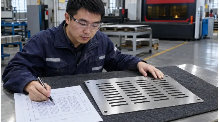
The most common DFM failure in stainless steel cutting involves hole diameters that are too small for the material thickness.
As a general rule for laser cutting, the minimum hole diameter should be equal to or greater than the material thickness (a 1:1 ratio). Attempting to laser-cut a 3mm hole in a 6mm stainless plate causes localized heat buildup, blowout, and a conical hole shape. If the hole is functional (like a bolt clearance hole), design it to meet this 1:1 ratio so it can be cut directly on the laser. If the small diameter is strictly required for the design, the supplier must move the part to a CNC mill for drilling, adding setup time, tool wear, and significant cost.
For slots, avoid sharp internal corners. Lasers must decelerate to cut a sharp 90-degree internal angle. Adding a small radius (e.g., R1.0mm) allows the machine to maintain a continuous feed rate.
Nesting and Allowances
Material yield directly impacts the per-part price, especially with heavy alloys like 316L. Nesting software arranges parts on a sheet to maximize yield, but your design choices can constrain this.
If you mandate a specific grain direction for cosmetic reasons, the software cannot rotate the parts freely, which lowers material utilization and increases your cost. Additionally, consider how parts stay attached to the sheet during cutting. Suppliers use “micro-joints” (small uncut tabs) to prevent parts from tipping up and crashing the laser head. Removing these tabs later requires manual grinding. If your design allows for a small protruding tab on a non-critical edge, you save the supplier the manual labor of grinding it flush.
Total Part Cost
When comparing quotes, look at the fully burdened cost. The total part cost breaks down into material, programming, setup, cutting runtime, consumables (high-pressure N2 gas), post-processing, and inspection.
In prototyping or low volumes, setup time and programming dominate the cost. Consolidating material thicknesses across your assembly allows the supplier to nest all your parts on one sheet, cutting setup fees. At volume production, machine runtime and manual post-processing (deburring, tapping) become the primary cost drivers.
TZR DFM Cost Reduction Case Study
During a routine TZR DFM review, we identified a major cost driver in a client’s motor bracket design:
- Material: 6mm 304 Stainless Steel.
- Volume: 500 units/month.
- Original Design: Included four 4mm threaded holes. Because 4mm is less than the 6mm thickness, the holes could not be reliably laser-cut. The routing required laser cutting the outer profile, moving the parts to a CNC mill, spotting, drilling, and tapping the holes.
- DFM Adjustment: We recommended changing the assembly to use standard M6 hardware. The hole diameters were increased to 6.5mm.
- Result: The 6.5mm holes met the >1:1 thickness ratio and could be cleanly laser-cut in the same operation as the profile. The secondary CNC drilling operation was entirely eliminated. Total part cost was reduced by 32% solely by eliminating the secondary machining center setup.
Confirm Supplier Capability and Final Inspection
A low quote means nothing if the supplier uses the wrong process or skips secondary operations to hit the price point. To ensure the final parts match your assembly needs, you must align the RFQ package, the manufacturing routing, and the inspection criteria before issuing the purchase order.
RFQ Details
A complete Request for Quote (RFQ) prevents assumptions. Sending only a 3D CAD model is a common mistake; a STEP file tells the machine what to cut, but the 2D PDF print tells the machinist what to measure.
Your RFQ package must include:
- Exact Material Specs: Grade (e.g., 304 vs. 316L), condition, and starting surface finish (e.g., 2B, No. 4 brushed, or 8K mirror).
- Complete Files: 3D CAD files for programming and 2D PDFs for tolerances, datum references, and threaded hole callouts.
- Processing Requirements: Clear notes on edge breaking, surface protection, and chemical post-processing.
- Logistics: Batch quantities, expected lead times, and specific packaging requirements.
Process Confirmation
Before accepting a quote, ask the supplier to confirm their intended manufacturing routing. You need to know if their process can stably produce your critical features across the entire batch, not just on a single prototype.
Review the hard-to-machine areas and machining allowances together. If your print requires an H7 reamed hole and the supplier intends to only use a laser cutter, they will fail your quality inspection. At TZR, we provide a DFM review alongside our quotes to explicitly state which features will be cut directly and which require secondary CNC machining.
Additionally, clarify what is done in-house versus outsourced. Outsourced chemical passivation or heat treatment doesn’t just add lead time; it introduces a black box in quality control. Always clarify what is done internally to ensure accountability.
Inspection and Acceptance
Define how the parts will be inspected and accepted. A common dispute occurs when a client measures a part using a CMM (Coordinate Measuring Machine) upon receipt, while the supplier used hand calipers on the shop floor.
- Inspection State: Clarify if the dimensional inspection happens immediately after the primary cut, or after final surface treatments (which can alter hole diameters or material thickness).
- Documentation: For critical industrial applications, require Material Test Reports (MTRs, such as EN 10204 3.1 certificates) to prove the chemical composition of the stainless steel. Demand inspection reports for the First Article Inspection (FAI) before volume production begins.
- Packaging: Stainless steel cosmetic finishes are easily destroyed by ocean freight vibration if parts rub together. Specify if parts need to be paper-interleaved, individually bubble-wrapped, or packed in custom foam trays to survive international transit.
Don’t let a vague RFQ inflate your costs or delay your assembly line.
Stop guessing how your supplier will interpret your drawings. Send your STEP files and 2D PDFs to the engineering team at TZR for a comprehensive, no-obligation DFM review. We will identify cost-saving opportunities, define a precise process routing, and deliver a transparent quote built for actual production.