
 French
  English
  Spanish
  German
  Russian
  Italian
Le cumul des tolérances désigne l'accumulation des variations dimensionnelles au sein d'un ensemble composé de plusieurs pièces. À mesure que les composants s'assemblent, leurs écarts de fabrication admissibles s'additionnent. Si ce phénomène n'est pas maîtrisé, ces écarts cumulés peuvent entraîner un grippage des pièces, des fuites ou un mauvais ajustement, même lorsque chaque composant a passé avec succès le contrôle qualité.
Un modèle CAO part du principe d'une géométrie parfaite. Or, l'atelier de production fonctionne dans le cadre de limites physiques admissibles. Lorsque les ingénieurs se concentrent uniquement sur les tolérances de pièces isolées, ils négligent la réalité physique de l'assemblage final.
La gestion de cette accumulation ne se résume pas à un simple exercice mathématique. Comprendre comment maîtriser ces variables permet d'assurer une transition en douceur entre la phase de prototypage initial et la production en série à haut rendement.
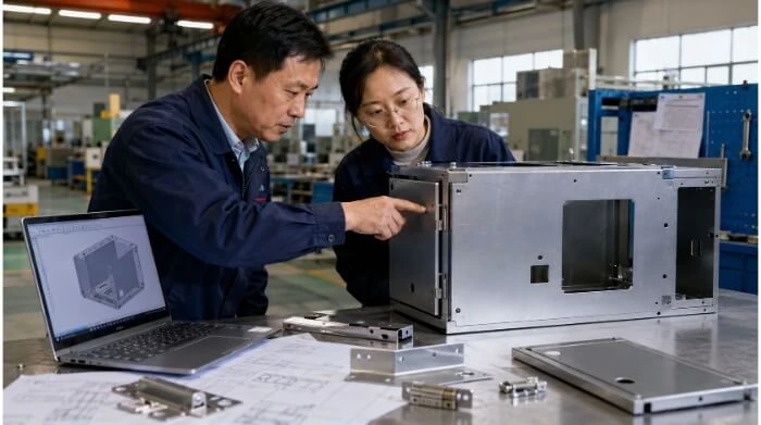
C'est l'ajustement lors du montage qui détermine la tolérance
Avant d'attribuer des cotes à un dessin, vous devez déterminer les contraintes physiques auxquelles l'assemblage est soumis. Le choix de la stratégie de tolérance appropriée dépend de la manière dont les pièces interagissent dans la réalité.
Clairance fonctionnelle
Un assemblage statique boulonné nécessite une approche différente de celle d'un mécanisme coulissant de précision. Pour un ajustement glissant standard sur un arbre de 10 mm, un Classe de tolérance ISO H7/g6 offre un jeu compris entre environ 0,005 mm et 0,023 mm.
Votre calcul d'empilement doit permettre de vérifier que les variations de fabrication cumulées permettront de maintenir cet écart spécifique. Si vous ne tenez pas compte de cet élément, vous obtiendrez généralement un assemblage soit trop lâche pour fonctionner, soit trop serré pour être monté.
Surfaces de contact
Lorsque deux composants sont assemblés par des vis, les dimensions linéaires ne sont pas les seules variables. Les tolérances de forme, telles que planéité et parallélisme ont une incidence directe sur l'assemblage et doivent être pris en compte dans le calcul de la pile.
Par exemple, un Courbure de 0,5 mm sur un support en tôle peut modifier l'alignement des trous à l'extrémité opposée. Cela entraîne des interférences physiques, même si les centres linéaires des trous sont usinés avec une précision parfaite, conformément aux spécifications.
Contact d'étanchéité
Les joints d'étanchéité pour fluides et gaz reposent sur une compression contrôlée du matériau. Pour les applications standard de joints toriques statiques, les conceptions mécaniques visent généralement une Taux de compression de 20% à 30%.
Si la profondeur de la rainure usinée et l'épaisseur de la face d'appui s'additionnent dans le même sens, la compression finale peut se situer en dehors de cette plage fonctionnelle. Cela entraîne généralement une fuite catastrophique ou l'écrasement du joint.
Pièces mobiles
Les composants rotatifs ou coulissants sont très sensibles à l'accumulation de erreurs de faux-rond et de concentricité. Lorsqu'un seul arbre de transmission traverse deux paliers distincts, la tolérance de position des alésages des deux paliers doit être calculée comme s'il s'agissait d'un seul et même système.
Si l'empilement entraîne un désalignement des alésages, l'arbre va se coincer. Cela augmente immédiatement le frottement et provoque une défaillance prématurée des roulements.
Risque lié à l'assemblage final
Évaluez le coût d'un défaut d'ajustement afin de déterminer le degré de rigueur que doit présenter votre stratégie de tolérance. Si un seul prototype présente un défaut, le principal coût réside dans le temps consacré à l'ingénierie.
Cependant, dans la production en série, un cumul de tolérances non maîtrisé qui entraîne un Taux de défaillance des modules 3% aura pour conséquence des rebuts importants, des coûts de retouche et des retards sur les chaînes de production.
Construire la pile autour de repères fonctionnels
La manière dont vous cotez un dessin en 2D influe directement sur la façon dont les tolérances s'accumulent au cours du processus de fabrication. Une stratégie de cotation bien pensée simplifie l'usinage et réduit au minimum les risques liés à l'assemblage.
Stratégie de Datum
Choisissez les points de référence en fonction de la manière dont la pièce est réellement montée dans l'assemblage final, et non en fonction de ce qui est le plus facile à mesurer. Pour les pièces usinées par CNC, un face fraisée à plat constitue une référence fiable tant pour le réglage que pour le contrôle final.
Pour les pièces en tôle, Évitez d'utiliser un bord courbé comme référence principale. si possible. Le retour élastique naturel entraîne de légères variations d'angle, ce qui amplifiera les erreurs de position pour tout motif de perçage mesuré à partir de ce pli.
Dimensions de référence
Le dimensionnement par rapport à la ligne de base fait référence à plusieurs caractéristiques par rapport à un seul bord ou plan de référence. Étant donné que l'opérateur et le contrôleur mesurent chaque caractéristique indépendamment l'un de l'autre à partir de la même origine, les tolérances ne s'additionnent pas entre les différentes fonctionnalités.
Cette méthode est particulièrement adaptée aux schémas de perçage complexes qui doivent s'aligner avec un seul composant d'assemblage. Elle permet également au fabricant d'atteindre plus facilement vos objectifs, ce qui conduit souvent à des tarifs plus compétitifs pour votre demande de devis.
Dimensions de la chaîne
Le cotage en chaîne consiste à mesurer une caractéristique directement à partir de la précédente. Dans cette méthode, la tolérance de chaque cote s'ajoute à celle de la suivante.
Une série de cinq trous, chacun présentant une tolérance de ±0,1 mm, peut entraîner un Erreur de position de ±0,5 mm pour le trou final par rapport au point de départ. Cette méthode n'est généralement utilisée que pour les éléments dont la distance entre deux points adjacents est nettement plus importante que leur emplacement global sur la pièce.
Légendes GD&T
Le cotage géométrique et les tolérances (GD&T) permettent un contrôle plus précis des caractéristiques fonctionnelles que les cotes traditionnelles en coordonnées X-Y. L'utilisation de légendes de « position réelle » permet de zone de tolérance cylindrique.
Cela permet d'obtenir jusqu'à 57% : zone de fabrication plus adaptée pour un élément circulaire par rapport à une zone de tolérance de cotes carrée. En élargissant la zone acceptable, vous réduisez le taux de rebut du fabricant et le temps consacré au contrôle. Cela se traduit directement par un prix unitaire plus bas sans compromettre la fonctionnalité de l'assemblage.
Fonctionnalités essentielles au bon fonctionnement
Considérez les tolérances comme une marge de fabrication. N'attribuez des tolérances plus strictes qu'aux caractéristiques spécifiques qui déterminent l'ajustement lors de l'assemblage.
Appliquer un tolérance globale de ±0,01 mm sur l'ensemble d'une pièce augmente les temps de cycle CNC et nécessite un contrôle 100%. Réservez les contrôles stricts aux trous de goupilles de centrage et aux ajustements des roulements, et appliquez des tolérances standard plus larges aux trous de passage afin de maîtriser les coûts de production.
Comment les processus de fabrication modifient les calculs
Les différentes méthodes de fabrication présentent des marges de tolérance naturelles totalement différentes. Un calcul d'empilement qui repose sur la précision du fraisage CNC échouera immédiatement si les pièces sont en réalité fabriquées à l'aide d'une presse plieuse.
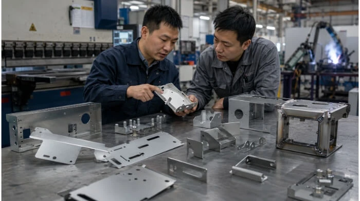
Profilés découpés au laser
Découpe au laser offre une excellente répétabilité, mais des déformations thermiques et des variations de la largeur de la tranchure persistent. Les tolérances standard des lasers industriels oscillent généralement autour de ±0,1 mm pour les métaux de faible épaisseur.
Lors de la conception d'assemblages en tôle à languettes et fentes, vous devez tenir compte de la micro-conicité de la poutre. Si plusieurs fentes sont découpées avec des dimensions légèrement inférieures à celles prévues en raison des variations thermiques, l'accumulation des interférences rendra l'assemblage final impossible sans un limage manuel.
Emplacements des brides déformées
Chaque pliage introduit une nouvelle variable. La tolérance de pliage s'accumule à une vitesse incroyable, car elle dépend de l'épaisseur du matériau, des réductions dues au pliage et du choix de l'outillage de la presse plieuse.
Si un enceinte en tôle Comme il comporte quatre coudes consécutifs, l'emplacement physique de la bride finale sera soumis à la variation cumulée de tous les coudes précédents. Le recours à un partenaire spécialisé dans la tôlerie permet d'atténuer ce problème. Une équipe d'ingénieurs compétents saura ajuster le facteur K du patron à plat afin d'absorber les variations naturelles de courbure, tout en maintenant l'empilement final dans les limites requises sans avoir à resserrer les tolérances d'emboutissage.
Insertion du matériel
Les éléments de fixation à enfoncer, tels que les écrous PEM et les entretoises, entraînent un décalage mécanique. Le trou poinçonné dans la tôle présente une tolérance, la tige de l'élément de fixation présente une tolérance, et le piston d'insertion exerce une force physique susceptible de déformer légèrement le matériau environnant.
Lors de l'alignement d'un circuit imprimé sur mesure comportant quatre entretoises enfoncées, cette erreur de position cumulée entraîne souvent filetages abîmés ou circuits imprimés fissurés. Le surdimensionnement des trous de passage sur la pièce d'accouplement constitue le moyen le plus économique d'atténuer ce risque spécifique lié au processus.
Déformation du châssis soudé
L'apport de chaleur provoque la dilatation du métal, tandis que le refroidissement entraîne une contraction imprévisible. Les assemblages soudés respectent rarement des tolérances dimensionnelles strictes dès leur sortie de la table de soudage.
Si votre assemblage nécessite une précision de ±0,2 mm sur l'ensemble d'un châssis soudé, le processus de fabrication de base ne permettra pas d'atteindre cet objectif. Vous devez ajouter marges d'usinage après soudage à votre plan, ce qui a une incidence considérable sur le prix final de l'appel d'offres.
Intégrer les modifications apportées aux matériaux et aux finitions
Un modèle CAO part du principe que les propriétés des matériaux sont uniformes et que les finitions ont une épaisseur nulle. En atelier, les irrégularités des matières premières et les revêtements appliqués ajoutent des couches cachées à votre cumul de tolérances.
Variation de l'épaisseur de la tôle
La tôle brute n'est pas parfaitement uniforme. Une tôle d'aluminium standard de 2 mm sort de l'usine avec une variation d'épaisseur admissible, souvent environ ±0,08 mm selon la jauge.
Si votre conception prévoit d'empiler cinq de ces plaques les unes sur les autres, l'épaisseur totale peut varier de près d'un demi-millimètre avant même que l'usinage ne commence.
Dos d'âne
La tôle a naturellement tendance à reprendre sa forme plane après être sortie de la matrice de la presse plieuse. Les matériaux plus durs, comme l'acier inoxydable 304, présentent un retour élastique bien plus important que l'aluminium 5052.
Cette variation angulaire entraîne empilement linéaire des positions en fonction de la distance. Une bride dont l'équerrage est dévié de seulement 0,5 degré entraînera un décalage du trou d'accouplement situé à 100 mm de là, qui sortira complètement de sa plage de tolérance prévue.
Dilatation thermique
Les métaux se dilatent et se contractent en fonction des variations de température. L'aluminium se dilate environ deux fois plus vite que l'acier.
Si vous concevez un assemblage à tolérances serrées comportant des métaux différents, un empilement qui fonctionne parfaitement dans une salle d'inspection à 20 °C peut entraîner un grippage ou des interférences lorsqu'il fonctionne dans un compartiment moteur à 80 °C.
Contrainte sur les matériaux
L'usinage de pièces épaisses ou la découpe au laser d'acier laminé à froid libère des contraintes internes emprisonnées. À mesure que le matériau se détend, la pièce se déforme ou se courbe naturellement.
Cela ajoute une planéité inattendue et des variations de profil à l'empilement de l'assemblage. En spécifiant matériaux détendus ou bien l'ajout d'étapes de recuit intermédiaires s'avère utile, mais allonge les délais de fabrication.
Accumulation de dépôts
Revêtement en poudre ajoute généralement 50 à 100 microns (0,05 mm – 0,1 mm) par surface. Si vous appliquez un revêtement en poudre sur un trou usiné avec précision, le diamètre intérieur diminue d'une valeur égale à deux fois l'épaisseur du revêtement.
Si vous ne tenez pas compte de cet épaisseur supplémentaire dans votre calcul d'épaisseur totale, cela compromettra les ajustements serrés et nécessitera des opérations manuelles coûteuses de retaraudage ou d'alésage sur la chaîne de montage.
Marge de placage
Les traitements chimiques tels que anodisation ou zincage réduire l'épaisseur de la pièce, généralement comprise entre 5 et 25 microns. Cela suffit toutefois à faire dévier un ajustement serré strict du roulement hors des tolérances spécifiées.
Pour y parvenir, veillez à toujours ajouter une note claire à votre dessin technique : « LES DIMENSIONS ET TOLÉRANCES S'APPLIQUENT APRÈS LE PLAQUAGE » ou « PERÇAGE DU MASQUE AVANT LE PEINTURE PAR POUDERISATION. » Cela permet d'éliminer toute ambiguïté au cours du processus d'appel d'offres et d'éviter des retouches coûteuses.
Choisissez la bonne méthode d'empilement
La manière dont vous calculez l'accumulation des tolérances a une incidence à la fois sur le coût des pièces et sur le risque lié à l'assemblage. La méthode à adopter dépend du volume de production, de la fonction de la pièce et du niveau de risque de défaillance que vous êtes prêt à accepter.
| Méthode de calcul | Meilleure application | Style « Tolérance » | Coût de fabrication |
|---|---|---|---|
| Analyse du scénario le plus défavorable | Prototypes, systèmes de sécurité essentiels | Extrêmement serré | Haut |
| Racine carrée de la somme des carrés (RSS) | Assemblages en série | Modéré / Statistique | Rentabilité |
| Simulation de Monte-Carlo | Assemblages 3D complexes | Sélectif / Ciblé | Optimisé |
Analyse du scénario le plus défavorable
L'analyse du pire scénario part du principe que chaque cote de l'assemblage atteint simultanément sa limite maximale ou minimale. Cette méthode consiste à additionner directement toutes les tolérances individuelles.
Formule :
T_wc = T_1 + T_2 + … + T_n
Où ?
T_wc = tolérance totale dans le pire des cas
T_1, T_2, …, T_n = tolérances des pièces individuelles
Cette méthode offre le plus haut niveau d'interchangeabilité des pièces. Elle s'avère utile lorsque chaque assemblage doit s'ajuster sans se fonder sur des probabilités statistiques.
Cependant, l'analyse du scénario le plus défavorable impose souvent des tolérances très strictes pour chaque pièce. Cela augmente les coûts d'usinage, le travail d'inspection et le risque de rebut. Cette approche convient bien aux prototypes en petites séries et aux pièces critiques pour la sécurité, mais elle s'avère souvent trop coûteuse pour la production industrielle standard.
Calcul du RSS
La méthode de la somme des carrés des racines repose sur une approche statistique. Elle part du principe que toutes les dimensions n'atteindront pas leur pire valeur en même temps.
Formule :
T_rss = √(T_1² + T_2² + … + T_n²)
Où ?
T_rss = tolérance statistique totale
T_1, T_2, …, T_n = tolérances des pièces individuelles
sqrt = racine carrée
Le RSS permet d'élargir les tolérances des pièces individuelles tout en conservant un taux de réussite élevé lors de l'assemblage. Cela permet de réduire la difficulté d'usinage et de diminuer les coûts de contrôle.
Cette méthode est généralement plus adaptée à la production en série. Elle permet aux ingénieurs d'éviter de fixer des tolérances trop strictes pour chaque cote lorsque les données réelles de production ne justifient pas un tel niveau de contrôle.
Simulation de Monte-Carlo
La simulation de Monte-Carlo est utilisée pour les assemblages complexes où un simple calcul de tolérance unidirectionnel ne suffit pas. C'est souvent le cas lorsque des pièces tournent, coulissent, se courbent ou interagissent selon plusieurs axes.
Au lieu d'utiliser une seule équation fixe, la simulation de Monte Carlo effectue de nombreux essais d'assemblage virtuels. Une distribution de probabilité est attribuée à chaque dimension.
Exemple de répartition :
Distribution normale = N(moyenne, É.T.²)
Où ?
moyenne = moyenne du processus
SD = écart-type
La simulation met en évidence les dimensions qui présentent le plus grand risque de défaillance. Cela permet aux ingénieurs de resserrer uniquement les tolérances qui ont une incidence réelle sur l'ajustement final.
Cette méthode permet de resserrer les tolérances de manière sélective. Elle évite de dépenser de l'argent pour des caractéristiques qui n'ont pas d'incidence significative sur le fonctionnement de l'ensemble.
Capacité du processus
Le cumul des tolérances ne doit pas reposer uniquement sur la théorie. Les données réelles d'atelier sont plus utiles lorsque le fournisseur dispose d'un historique de production stable.
L'indice de capacité du processus, ou Cpk, mesure la capacité d'un processus à maintenir une dimension entre les limites supérieure et inférieure de spécification.
Formule :
Cpk = min((limite supérieure de la plage de mesure – moyenne) / (3 × écart-type), (moyenne – limite inférieure de la plage de mesure) / (3 × écart-type))
Où ?
Cpk = indice de capacité du processus
USL = limite supérieure de spécification
LSL = limite inférieure de spécification
moyenne = moyenne du processus
SD = écart-type
min = la plus petite des deux valeurs obtenues
Un processus dont le Cpk est supérieur ou égal à 1,33 est généralement considéré comme stable pour de nombreuses applications de production. Cela signifie que les pièces sont statistiquement regroupées près du centre de la plage de tolérance.
Le fait de tenir compte des capacités réelles des fournisseurs rend le calcul cumulé des tolérances plus concret. Cela permet d'éviter la surconception et facilite l'établissement de devis précis par les fabricants à partir du dossier d'appel d'offres.
Réduire les coûts grâce à une gestion plus intelligente des tolérances
Chaque décimale figurant sur un dessin technique a une incidence financière directe. Une gestion intelligente des tolérances vous permet d'obtenir un ajustement parfait lors de l'assemblage, tout en réduisant délibérément les coûts de fabrication et de contrôle qualité.
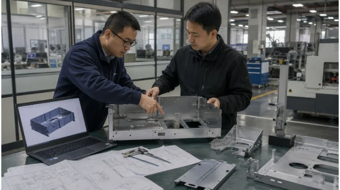
Coût des tolérances serrées
Le coût de fabrication n'évolue pas de manière linéaire avec la précision. Resserrer une tolérance linéaire de ±0,1 mm à ±0,01 mm ne prend pas simplement un peu plus de temps. Cela oblige souvent le fabricant à abandonner les avances de fraisage standard et à recourir à des techniques spécialisées telles que la rectification ou l'électroérosion à fil.
Cette évolution du processus de fabrication peut facilement tripler le coût unitaire. Cela réduit également le nombre de fournisseurs compétents à votre disposition et allonge vos délais de livraison. En vous appuyant autant que possible sur des tolérances standard (comme celles de la norme ISO 2768-m), vous vous assurez que les pièces peuvent souvent être livrées plusieurs semaines plus tôt.
Resserrement sélectif des tolérances
Au lieu de réduire la bande de tolérance de manière uniforme sur toutes les pièces d'un ensemble, identifiez la pièce dont la fabrication précise est la moins coûteuse.
Par exemple, respecter une tolérance serrée de ±0,02 mm sur une simple goupille tournée est très rentable. En revanche, respecter cette même tolérance de ±0,02 mm sur un alésage profond à l'intérieur d'un boîtier massif et soudé revient extrêmement cher. Répartir la charge liée à la précision aux composants les plus faciles et les moins coûteux à contrôler.
Planification des rencontres
Le cumul des tolérances dépend fortement de la manière dont la pièce est maintenue dans la machine. Les éléments usinés en un seul serrage ne subissent que l'erreur de positionnement de la machine-outil elle-même (souvent de l'ordre de quelques microns seulement).
Lorsqu'une pièce doit être retournée ou déplacée vers un nouveau dispositif de fixation, l'erreur de configuration est immédiatement ajoutée à la pile. Concevoir les pièces de manière à ce que toutes les caractéristiques d'assemblage essentielles au fonctionnement puissent être usiné d'un seul côté Cela élimine naturellement une source majeure de variation cumulée.
Effort d'inspection
Les tolérances serrées ne nécessitent pas seulement plus de temps pour l'usinage ; leur mesure prend également beaucoup plus de temps. Une cote standard de ±0,1 mm peut être vérifiée en atelier en quelques secondes à l'aide de pieds à coulisse étalonnés.
Une cote de position réelle de ±0,01 mm nécessite un Machine à mesurer tridimensionnelle (MMT) une configuration adaptée et un contrôleur qualité dédié. En assouplissant les tolérances grâce à une gestion intelligente de l'empilement, vous réduisez le goulot d'étranglement lié au contrôle qualité et raccourcissez votre délai de livraison global.
Erreurs courantes liées au cumul des tolérances
Même les équipes d'ingénieurs expérimentées négligent parfois les contraintes physiques de l'atelier lorsqu'elles élaborent leurs modèles d'empilement. Évitez ces erreurs courantes de conception afin de prévenir les retards de production.
Tolérance excessive
Lorsqu'un calcul d'empilement dans le pire des cas échoue sur le papier, la réaction immédiate consiste souvent à réduire sans discernement de 50% les tolérances de chaque pièce de l'ensemble.
C'est ce qu'on appelle capacité à gérer la panique. Cela « corrige » les calculs mathématiques dans le logiciel de CAO, mais cela garantit un devis exagérément élevé. Au lieu de réduire les tolérances, modifiez le système de cotation ou optez pour un calcul RSS si le volume de production le justifie.
Données manquantes
Les logiciels de CAO effectuent naturellement leurs mesures à partir d'un point d'origine absolu. Sur un établi physique, cette origine mathématique n'existe pas.
Si vous n'indiquez pas explicitement de repères physiques (tels qu'une face usinée spécifique ou un alésage principal) sur votre plan, le fabricant choisira ses propres repères en fonction de ce qui est le plus facile à serrer dans l'étau. Cela entraîne presque toujours un cumul de tolérances imprévisible lors de l'assemblage final — et litiges relatifs aux pièces rejetées car l'inspecteur et le machiniste ont effectué leurs mesures à partir d'origines différentes.
Dimensionnement des chaînes
Le fait d'enchaîner les dimensions de bout en bout garantit que chaque erreur de traitement s'accumule.
Malgré cela, le dimensionnement des chaînes reste l'une des causes les plus fréquentes de rejet des pièces lors des contrôles. À moins que vous ne conceviez spécifiquement un composant flexible tel qu'une chaîne d'entraînement, Utilisez toujours le cotage de référence pour les schémas de perçage et les points de fixation critiques.
Épaisseur du revêtement non prise en compte
Les ingénieurs effectuent souvent des calculs d'empilement en se basant sur les dimensions du métal nu, en oubliant que les traitements de surface augmentent le volume physique.
Une application standard de peinture en poudre permet d'ajouter facilement 100 microns d'épaisseur. Si une goupille de 10 mm est conçue pour s'insérer dans un alésage de 10,1 mm, l'application d'un revêtement en poudre sur les deux pièces entraînera un conflit de dimensions, ce qui nécessitera une retouche manuelle coûteuse pour l'assemblage.
Conclusion
La réussite d'un assemblage mécanique ne repose pas uniquement sur les calculs mathématiques de la CAO. Elle nécessite d'aligner votre stratégie de cotation sur le comportement physique des machines à commande numérique, des presses plieuses et des matières premières. En appliquant des tolérances sélectives et en comprenant comment les variations de fabrication s'accumulent, vous pouvez garantir des ajustements d'assemblage fiables tout en réduisant activement les coûts de production.
Vous n'êtes pas sûr que votre assemblage résiste à la production en série ? N'attendez pas le jour du montage pour le découvrir.
Chez TZR, notre équipe d'ingénieurs s'appuie sur 10 ans d'expérience dans la fabrication de tôles de précision et l'usinage CNC pour faire le lien entre la théorie de la conception et la mise en œuvre en atelier. Nous examinons minutieusement la géométrie des pièces, ajustons les plans de dépliage et fournissons des recommandations en matière de conception pour la fabrication (DFM) afin d'éviter tout problème d'empilement avant même de procéder à la découpe du métal.
Envoyez vos plans techniques à TZR pour bénéficier d'une analyse DFM gratuite. Nous identifierons les risques liés aux tolérances et vous aiderons à optimiser votre appel d'offres dès aujourd'hui.