
 English
 Spanish
 German
 Russian
 Italian
 French


The most effective way to reduce CNC machining costs is to minimize machine cycle time and setup labor. You can achieve this by standardizing internal radii, relaxing non-critical tolerances, avoiding deep pockets, and choosing highly machinable materials to eliminate expensive custom tooling.
However, applying these design for manufacturability (DFM) principles blindly won’t work. From reviewing thousands of RFQs on the factory floor,we see engineers frequently make design compromises that don’t actually move the financial needle.
To lower your quote effectively, you must first diagnose exactly what is making your specific part expensive. Use this quick reference table to identify your primary cost drivers before adjusting your CAD files:
| Common Situation | What to Check First |
| High unit price for prototypes | CAM programming, workholding setup, and first-article inspection time. |
| Multiple deep pockets or sharp internal corners | Tool diameter, extended tool reach, and slow material removal rates. |
| Requires machining from multiple angles | Part orientation, primary locating surfaces, and the number of setups. |
| Tight tolerances applied across the entire drawing | Functional tolerances, surface roughness requirements, and inspection scope. |
| A large volume of material is cut away | Stock size selection and alternative manufacturing routes. |
| Frequent rush orders or design revisions | Completeness of RFQ data, finalization of files, and delivery schedules. |
Identify What Drives Your CNC Machining Costs
Stop assuming a fixed cost breakdown for every project. Depending on your order volume and part geometry, the main expense could be the setup time, the actual cutting time, or the post-processing. Identifying the correct bucket prevents you from making design changes that don’t actually move the financial needle.
Programming and Setup
Before a spindle even turns, an engineer must program the toolpaths (CAM), design or assign workholding fixtures, set tool offsets, and run a first-article inspection to verify dimensions.
This setup labor is a fixed cost. Whether you order one prototype or a batch of 500, the preparation time remains largely the same. For low-volume runs, setup and programming often account for over 50% of the unit price. Reducing the number of unique setups—by designing features that can be machined from a single direction—is the fastest way to drop prototype costs.
Machining Time
Machining time is driven by material removal rates, the number of tool changes, and the speed at which the machine can safely cut.
A physically small part is not automatically cheap to machine. If a compact design features deep, narrow channels, the operator must use fragile, extended-reach micro-tools. To prevent tool deflection and chatter, feed rates must be drastically reduced—often by 50% or more. You end up paying for the extended machine hours, regardless of the part’s footprint.
Additional Operations
Post-processing steps add discrete layers of cost. This includes manual deburring, heat treatment, surface finishing (like anodizing, plating, or bead blasting), and formal metrology reports (like CMM inspection).
When comparing quotes from different suppliers, verify what is actually included. A surprisingly low quote might exclude mandatory material certificates or assume a basic “as-machined” finish, leaving you with hidden costs later when strict tolerances or custom masking are applied.
Simplify Features That Increase CNC Machining Time
Design choices dictate the tools a machinist must use. By making minor adjustments to the geometry, you allow the shop to use larger, standard tools that remove material faster and wear out slower.
Internal Corners
When designing internal cavities, it is critical to distinguish between vertical wall corners and floor radii.
A rotating milling tool naturally leaves a radius on vertical internal corners. Requesting a perfectly sharp 90-degree internal corner means the shop must switch to a slow secondary operation like Wire EDM or broaching. Unless that sharp corner is strictly required for a sliding mechanism or an aerospace fluid seal, it adds unnecessary cost.
To reduce cycle time, specify a corner radius slightly larger than the standard tool radius (for example, specify an R3.5mm corner instead of R3.0mm for a 6mm end mill). This allows the tool to glide smoothly through the corner without stopping to pivot. If a square component must fit into the cavity, use dog-bone corner reliefs instead of demanding a sharp machined angle.
Deep Pockets
A pocket becomes exponentially more expensive when its depth exceeds 3 to 4 times the diameter of the tool required to cut its internal corners. Extended-reach tools vibrate easily. To counter this, machinists must take multiple shallow passes, heavily inflating cycle time and increasing the risk of tool breakage.
Machine shops actively factor this tool-breakage risk into your unit price. To lower the quote, evaluate if you can reduce the cavity depth, widen the internal corner radii to accommodate a thicker, stiffer tool, or redesign the geometry as two separate components that bolt together.
Holes and Threads
Stick to standard drill and tap sizes. A non-standard hole dimension forces the machinist to use circular interpolation with a smaller end mill, which takes significantly longer than a simple plunge with a standard drill bit.
For threaded holes, strictly separate the drill depth from the effective thread engagement length. Threading deeper than 2.5 to 3 times the hole diameter rarely increases fastening strength; it only raises the risk of snapping a tap inside the part. Suppliers routinely charge a premium for this scrap risk, because a broken tap at the final stage usually means the entire piece is scrapped.
For blind holes, always leave an unthreaded clearance zone at the bottom (at least half the hole diameter) to allow metal chips to pack. Removing this simple chip clearance often forces the shop to manually tap the threads, driving up labor costs unnecessarily.
Reduce Setups and Improve Machining Stability
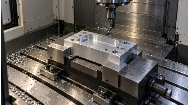
Every time a machinist has to open the vise, rotate the part, and re-indicate the datums, your cost goes up. Each manual setup not only adds labor time but also introduces a significant risk: tolerance stacking. Designing parts that are stable to hold and easy to machine in fewer operations is one of the most effective ways to control your final quote and guarantee dimensional accuracy.
Machining Directions
Review your part for side holes, angled features, and undercut geometries. Each unique face that requires machining usually dictates an additional setup.
The hidden cost of multiple setups isn’t just the operator’s time—it’s the loss of precision. If your drawing requires strict concentricity or true position between two features, but those features are machined in different setups, the shop has to fight tolerance drift.
To guarantee that precision across a part flip, the supplier will drastically increase the price to cover the anticipated scrap rate. Whenever possible, consolidate critical features and mounting holes to a single primary face.
Clamping and Rigidity
Before a tool can cut metal, the machinist needs a solid way to grip the raw material. Parts with entirely curved outer profiles, excessively thin walls, or slender structures vibrate during machining.
To prevent this chatter, the shop is forced to machine custom soft jaws or run the machine at heavily reduced feed rates. You can completely eliminate these custom fixture costs by discussing clamping strategies with your supplier early.
A standard industry trick is to add a flat sacrificial feature—like a temporary clamping tab or a straight 2mm base—directly into your CAD model. This gives the standard vise a firm grip during the heavy cutting phases, and the tab is simply faced off in the final step.
Machine Selection
Do not base your sourcing decisions purely on equipment hourly rates. A standard 3-axis mill might cost $40 an hour to run, while a 5-axis machining center or a mill-turn lathe might command $120 an hour.
However, looking only at the hourly rate is a trap. If a complex housing requires five separate setups on a cheaper 3-axis mill, the combined cost of manual labor, setup time, and custom fixture blocks will usually far exceed the cost of running it on a 5-axis machine that can complete the part in a single operation (“done-in-one”). Evaluate the total manufacturing route—including setup time, cutting hours, and precision reliability—rather than just the hourly fee.
| Content | Process Information |
| Original Problem | A sensor housing required 4 distinct setups on a 3-axis mill because connector ports were distributed across three different side walls. The rounded bottom also required expensive custom curved vise jaws. |
| Approved Change | Moved all connector ports to the top face. Added a straight 2mm sacrificial flat base to the CAD model to allow standard vise clamping. |
| Cost Impact | Setups dropped from 4 to 2. Custom fixture costs were eliminated. Total machining and setup fees dropped by roughly 30%. |
| Validation | The internal cavity volume, sensor mounting points, and overall footprint remained fully functional and within required specifications. |
Specify Only the Precision Your Part Needs
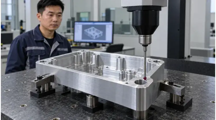
Over-specifying tolerances and finishes is the fastest way to inflate a CNC quote. Tighter precision dictates slower machining passes, frequent tool changes, constant manual CMM measurement, and higher scrap allowances.
Functional Tolerances
Not every dimension on your drawing carries the same functional weight. A bearing press-fit or an O-ring groove requires strict geometric control; the outer profile of an internal bracket does not.
A common trap is the “blanket tolerance” in the drawing’s title block. If your title block demands ±0.01mm (0.0004″) globally, mature machine shops will either instantly reply with a “No Quote” or hit you with an exorbitant “F-U price” to make the headache worth it.
To get the best pricing, apply tight tolerances strictly to functional mating surfaces. For the rest of the component, rely on standard block tolerances (such as ISO 2768-m). By zoning your tolerances, you signal to the shop exactly where they need to slow down, allowing them to machine the rest of the part at maximum speed.
Surface Roughness
Surface roughness (Ra) requirements should directly match the application. A smooth Ra 0.8 µm (32 µin) finish is critical for dynamic seals or sliding components. However, achieving this finish physically requires the machine to take multiple overlapping passes with a microscopic step-over, multiplying the machine time.
For non-contact surfaces or internal structural areas, a standard “as-machined” finish (typically around Ra 3.2 µm or 125 µin) works perfectly and costs nothing extra. Never apply strict roughness callouts universally across the entire 3D model.
Finishing Requirements
Secondary operations like bead blasting, hard anodizing, or powder coating extend lead times and introduce minimum lot charges. But the real hidden cost here is masking.
If you require specific areas to remain uncoated—such as electrical grounding patches or tight-tolerance threaded holes—the shop must manually apply custom masking tape or insert individual silicone plugs into every single hole before dipping. This manual prep work adds up rapidly.
In some cases, the labor cost to manually plug 50 small threaded holes exceeds the actual CNC machining time of the part. If masking is unavoidable, consolidate the un-plated areas into one simple geometric zone rather than scattering them across the component.
Finally, always clarify on your RFQ whether your strict tolerances apply before or after the surface treatment. Finishes like hard anodizing can add up to 0.05mm (0.002″) to the material surface, which will instantly push a tight-tolerance bore out of spec if not accounted for during the machining stage.
Choose Materials and Stock for Lower Total Cost
The raw material itself usually accounts for a smaller percentage of the total quote than most engineers expect. The true financial impact of your material choice lies in how it behaves on the machine bed, how much of it gets turned into scrap chips, and whether its starting dimensions force the shop to perform high-risk roughing operations.
Material Selection
Do not base your material choice solely on the price per kilogram. You must evaluate the material’s machinability rating.
For instance, 304 Stainless Steel might seem like a robust, cost-effective choice on a spreadsheet. However, it work-hardens quickly, wears out carbide tooling rapidly, and forces the machinist to run the spindle at significantly slower feeds and speeds compared to Aluminum 6061 or free-machining Brass.
Always define your baseline engineering requirements first (yield strength, corrosion resistance, operating temperature). If a highly machinable alternative meets these specs, propose it—but ensure any material substitution is formally approved by the engineering team, not just dictated by the purchasing department based on ease of cutting.
Stock and Allowances
Machine shops buy raw material in standard fractional or metric plate, bar, and tube dimensions. If your part is exactly 51mm thick, the shop cannot use a standard 50mm plate. They must order 60mm stock and spend expensive machine time milling away 9mm of solid metal.
But the wasted machine time isn’t even the biggest problem—material distortion is. When you aggressively hog out heavy layers of material from one side of a billet, you release internal stresses, causing the metal to warp like a banana.
To keep the part flat, the machinist must slowly shave material off alternating sides or add expensive thermal stress-relief cycles. Whenever possible, design your maximum outer dimensions to sit comfortably within standard stock sizes, leaving just a 1-2mm allowance for a quick, low-stress cleanup pass.
Alternative Processes
Sometimes the best way to reduce CNC machining costs is to stop CNC machining the entire part. Hogging out 80% of an aluminum block to create a thin-walled enclosure is an incredibly inefficient use of both material and spindle time.
Evaluate whether the component can be split. You can often use rapid, cost-effective processes like sheet metal fabrication, extrusion, or casting for the bulk of the body, and only use CNC machining for the specific interfaces that require strict tolerances. Evaluate the total cost including setup, primary fabrication, secondary machining, and final assembly.
| Content | Process Information |
| Original Problem | A deep electronics enclosure was designed to be milled from a solid block of Aluminum 6061. Over 85% of the raw billet was machined away into chips, resulting in high material waste and high risk of wall distortion. |
| Approved Change | At TZR, we transitioned the design to a bent Aluminum 5052 sheet metal body. Only the front sensor-mounting flange (requiring an O-ring groove and tight-tolerance bores) was CNC machined, then riveted to the sheet metal chassis. |
| Cost Impact | Machine cycle time dropped drastically. Raw material costs dropped by 70%. The total unit cost was reduced by over 60%, even after accounting for assembly labor. |
| Validation | The two-part assembly successfully passed the required IP67 water-ingress testing, and the internal PCB mounting points remained within the necessary functional tolerances. |
Improve RFQs and Plan Orders More Efficiently
A high quote is often a symptom of missing information. When a supplier looks at an incomplete RFQ, they see uncertainty. To protect their margins, they will automatically apply a risk premium to cover potential rework, assumed tight tolerances, and unstated finishing requirements.
Complete RFQs
Eliminate the guesswork from your RFQs. Provide a comprehensive data package upfront so the shop can calculate exact run times rather than worst-case scenarios. A complete RFQ must include: consistent 3D CAD models and 2D PDF drawings, specific material grades (with substitution permissions noted), order quantities, defined tolerance zones, surface finish specifications, and required inspection reports.
The Broker Premium: Be aware that many “instant-quote” digital manufacturing platforms act as brokers. They outsource your files to a hidden network of shops and apply a 20% to 40% algorithmic markup. Bypassing these middleman platforms and communicating directly with a source factory is often the fastest way to instantly reclaim that budget.
Always ask your direct supplier to provide two prices: one strictly “As Drawn,” and one with “Supplier DFM Suggestions.” This invites the machinist to point out exactly which feature is inflating the cost and gives you the option to adjust it.
Batch Sizes
Because CAM programming and machine setup are fixed costs, ordering a single prototype forces that one part to absorb 100% of the setup fee. As you increase the batch size, the setup cost is amortized across the entire run.
However, the ultimate cost reduction at scale comes from automation. When orders reach a certain volume (e.g., 500+ units) and the machining process is stable, factories can switch to “lights-out machining.” Utilizing robotic pallet changers, the machines can run unattended overnight.
Because the nighttime machine depreciation rate is significantly lower than daytime labor rates, your unit price drops substantially. Discuss blanket orders or scheduled split-deliveries with your supplier to unlock these volume efficiencies without holding massive inventory.
Production Planning
Locking in your final design early and communicating clearly with your manufacturing partner prevents expensive interruptions. Every time a drawing is revised after production has started, the shop must rewrite the CAM program, modify the fixtures, and potentially scrap the raw material that was already cut.
For stable, repeat orders, the programming, custom fixtures, and inspection routines are already established. Establish clear communication channels with your supplier to verify their actual capabilities before placing the order.
Supplier Communication Checklist:
- Do you machine this in-house, or do you outsource to a third party?
- Can you provide complete material traceability and inspection certs?
- Does your quote explicitly include deburring, masking, and standard packaging?
Pre-Approval Checklist for Design Changes:
- Does the modified design still meet all original functional and environmental requirements?
- Are the quantities, material grades, inspection terms, and delivery schedules identical across both the original and revised quotes?
- Are the savings from the CNC machining reduction offset by new costs (e.g., added assembly labor, new fasteners, or secondary processing)?
- Has a first-article prototype of the revised design been physically validated before moving to batch production?
Send us your CAD files, drawings, and order quantity. Our engineers can review the main cost drivers and suggest practical changes for your approval.