
 Italian
  English
  Spanish
  German
  Russian
  French
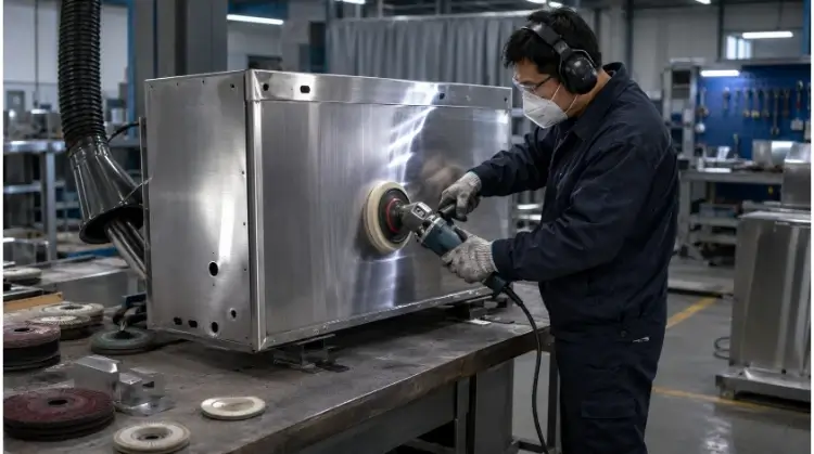
Per lucidare l'acciaio inossidabile, pulire accuratamente la superficie, quindi utilizzare abrasivi progressivi partendo dalla grana corrispondente al difetto più profondo (ad esempio, grana 80). Rifinire i graffi in modo sequenziale fino alla grana 1200 e terminare lucidando con composti abrasivi e coloranti per ottenere la finitura desiderata: spazzolata, satinata o a specchio.
La lucidatura industriale dell'acciaio inossidabile va ben oltre il semplice fatto di rendere lucido un componente. Nella produzione moderna, seguire la corretta sequenza di finitura superficiale è fondamentale per massimizzare la resistenza alla corrosione, soddisfare le rigorose specifiche relative al valore Ra (rugosità media) e tenere sotto controllo i costi complessivi di produzione.
Sia che si tratti della lavorazione di assemblaggi in lamiera saldata oppure Componenti lavorati a controllo numerico, questa guida va oltre i consigli generici e fornisce standard concreti da applicare in officina.
Flusso di lavoro standard:
Ispezionare la superficie → scegliere l'abrasivo iniziale → eliminare i difetti originari → rifinire ogni traccia di graffio → applicare la finitura finale → ispezionare e proteggere il pezzo.
| Risultato richiesto | Itinerario tipico | Requisito principale | Costo relativo |
| Spazzolato / N. 4 | Finitura abrasiva direzionale | Direzione delle fibre e campione approvato | Medio |
| Finitura satinata | Finitura con abrasivi a grana fine o con tessuto non tessuto | Consistenza della trama e della lucentezza | Medio |
| Specchio / N. 8 | Levigatura e lucidatura progressive | Aspetto e qualità della riflessione | Alto |
| Superficie igienica a basso Ra | Preparazione meccanica ed eventuale elettrolucidatura | Requisiti relativi a Ra e alla pulizia | Alto |
| Superficie saldata ripristinata | Livellamento delle saldature e uniformazione della finitura | Adattarsi alla superficie circostante | Da medio ad alto |
I requisiti relativi alla finitura dell'acciaio inossidabile hanno la precedenza sull'abrasivo
Il processo di lucidatura non inizia con una mola abrasiva. Le condizioni iniziali della materia prima e i requisiti tecnici finali determinano la scelta dell’abrasivo, le fasi di lavorazione e i metodi di controllo.
Superficie di partenza e finitura finale
Prima di scegliere gli utensili, gli operatori devono valutare le condizioni iniziali del pezzo. Tra gli stati iniziali più comuni figurano:
- Finiture standard da laminatoio (n. 1, 2B, BA) o lamiera pre-spazzolata.
- Saldature TIG/MIG in rilievo e relativa colorazione da calore.
- Come intervenire in caso di graffi, segni di stampo o scalfitture profonde.
- Segni lasciati dalla lavorazione con macchine utensili a controllo numerico (CNC).
- Corrosione superficiale a buche o ondulazioni localizzate del materiale.
- Superfici a specchio o decorative già esistenti che necessitano di riparazioni localizzate.
La profondità dei difetti presenti determina la grana iniziale in misura maggiore rispetto alla lucentezza desiderata. Ad esempio, la levigatura di una saldatura in rilievo su un pannello già spazzolato richiede un abrasivo iniziale molto più grossolano rispetto alla rimozione di lievi graffi da manipolazione da una lamiera laminata a freddo, anche se entrambi i pezzi richiedono la stessa finitura finale n. 4.
Designazioni di finitura, Ra e aspetto
Le denominazioni relative alle finiture industriali e i valori di rugosità superficiale (Ra) descrivono diversi aspetti di un componente.
| Finitura | Aspetto generale | Percorso produttivo tipico | Limitazione principale |
| N. 1 | Ruvido e opaco | Laminato a caldo, ricotto e decapato | Non è destinato a fungere da finitura decorativa |
| 2B | Liscio, a bassa riflettività | Laminato a freddo e rifinito a pelle | Non definisce un valore fisso di Ra |
| BA | Liscio e riflettente | Ricotto a caldo | Sensibile ai danni da lavorazione |
| N. 4 | Vena spazzolata direzionale | Finitura abrasiva | La grana e la lucentezza variano a seconda del fornitore |
| N. 8 | Specchio altamente riflettente | Levigatura fine e lucidatura | Richiede un'ispezione visiva |
Il valore Ra misura la rugosità superficiale a livello microscopico, mentre i valori n. 4 e n. 8 descrivono gli stati di lavorazione e l’aspetto visivo. Due pezzi possono presentare lo stesso valore Ra ma apparire completamente diversi a seconda della direzione di abrasione e della grana del materiale. Una finitura a specchio non può essere definita esclusivamente sulla base di un valore Ra basso.
Nota dell'ingegnere: Per evitare controversie con i fornitori, non basarsi esclusivamente sui valori Ra per i componenti decorativi. Specificare sempre la direzione della finitura (ad es., “Vena parallela al lato lungo”) e definire un campione fisico approvato (campione di riferimento) prima della produzione in serie.
Percorsi meccanici, chimici ed elettrochimici
I diversi processi di finitura superficiale risolvono problemi ingegneristici diversi e non possono sostituirsi direttamente l'uno all'altro.
| Processo | Scopo principale | Uso tipico |
| Lucidatura meccanica | Modificare la consistenza, eliminare i difetti e migliorare la lucentezza | Finiture spazzolate, satinate e a specchio |
| Decapaggio | Rimuovere le tracce di calore e gli ossidi di saldatura | Componenti saldati in acciaio inossidabile |
| Passivazione | Eliminare il ferro libero e migliorare le condizioni della superficie | Componenti soggetti a contaminazione o a requisiti di conformità |
| Elettrolucidatura | Ridurre i picchi microscopici e migliorare la pulibilità | Componenti per il settore medico, alimentare, dei fluidi e ad elevata purezza |
Passivazione È un trattamento chimico utilizzato per ripristinare lo strato di ossido, ma non costituisce una fase finale obbligatoria per tutti i componenti commerciali lucidati meccanicamente. L'elettrolucidatura rimuove il materiale per via ionica al fine di livellare i micro-picchi, operazione necessaria per il passaggio di fluidi ad alta purezza, ma raramente conveniente dal punto di vista economico per gli involucri decorativi standard.
Sequenza di abrasione, utensili e controllo del calore
Per ottenere risultati costanti sono necessari ambienti di lavoro controllati, una progressione rigorosa dell'abrasivo e una gestione termica adeguata. La lavorazione con abrasivi genera attrito e l'acciaio inossidabile reagisce male al calore non controllato.
Pulizia, strumenti specifici e sicurezza
Prima di qualsiasi contatto con il materiale abrasivo, è necessario pulire la superficie. Rimuovere i fluidi da taglio, gli adesivi delle pellicole laser, la polvere da officina, i residui di lucidatura e le scorie di saldatura. In caso contrario, i detriti si incastreranno nelle mole di lucidatura e graffieranno il metallo.
La contaminazione incrociata è una delle cause principali del rifiuto dei componenti in acciaio inossidabile. Gli stabilimenti devono utilizzare nastri abrasivi, mole lucidanti e spazzole metalliche dedicati esclusivamente all’acciaio inossidabile. L’uso di un utensile che in precedenza è stato impiegato per la lavorazione dell’acciaio al carbonio provoca l’incastro di particelle di ferro libere nella superficie dell’acciaio inossidabile. Una volta esposte all’umidità ambientale, queste particelle di ferro agiscono come celle galvaniche, causando la rapida formazione di macchie di ruggine localizzate. Questa è una delle cause principali per cui i componenti non superano i test in nebbia salina o i controlli di conformità della FDA durante l'ispezione finale.
Si applicano le norme standard di sicurezza e configurazione dell'officina: fissare il pezzo in lavorazione, verificare che il numero di giri al minuto (RPM) della mola corrisponda ai valori nominali dell'attrezzatura, mantenere in posizione tutte le protezioni della macchina, utilizzare i sistemi di aspirazione delle polveri e assicurarsi che gli operatori indossino adeguati dispositivi di protezione delle vie respiratorie e degli occhi.
Progressione di partenza da zero e da zero
La regola fondamentale della lucidatura meccanica consiste nell'utilizzare l'abrasivo iniziale più fine in grado di rimuovere efficacemente il difetto primario.
| Condizione iniziale | Intervallo di partenza tipico | Scopo principale |
| Saldatura in rilievo o danni gravi | grana 80–120 | Livellare la zona rialzata |
| Graffi lievi | grana 180–240 | Eliminare i danni visibili |
| Lievi graffi | grana 320–400 | Uniformare la superficie |
| Superficie in buone condizioni prima della lucidatura a specchio | grana 600 o più fine | Prepararsi alla lucidatura di precisione |
Nota: questi intervalli sono da considerarsi come valori di riferimento. Prima di procedere alla produzione, testare sempre la sequenza su un campione o su un’area non visibile.
La logica di avanzamento è rigorosamente sequenziale:
- Eliminare completamente il difetto originale con la grana iniziale.
- Pulire la superficie e l'area di lavorazione.
- Passare all'abrasivo successivo, più fine.
- Verificare la configurazione dei graffi presente sul precedente la sabbia viene eliminata completamente.
- Ripetere fino al raggiungimento del risultato desiderato.
Quando si punta a ottenere una finitura a specchio, ruotare la direzione di levigatura di 90 gradi tra una grana e l’altra aiuta gli operatori a verificare visivamente che i graffi precedenti siano stati eliminati. Per finiture spazzolate, la passata finale con l'abrasivo deve avvenire in modo uniforme e in un'unica direzione.
Ruote, mescole, pressione e calore
Gli utensili devono essere adeguati alla fase del processo. Per la levigatura del materiale si utilizzano ruote a contatto rigido o nastri in ceramica. Le ruote a lamelle e i piccoli utensili rotanti sono ideali per la rifinitura locale. Durante le fasi di lucidatura, dischi in tessuto rigido o in sisal, abbinati a un composto abrasivo (lucidatura di taglio), appiattiscono i graffi sottili, mentre dischi morbidi in flanella sfibrata, abbinati a un composto fine (lucidatura di colore), conferiscono la riflettività finale. Gli utensili in tessuto non tessuto per il trattamento delle superfici vengono solitamente utilizzati per la levigatura satinata.
Non scegliere i composti lucidanti basandosi esclusivamente sul colore. Le formulazioni dei composti neri, marroni, verdi e bianchi variano a seconda del produttore. Verificare con il fornitore la granulometria in micron e il metallo a cui sono destinati.
Il controllo termico è un requisito fondamentale. L’acciaio inossidabile presenta una bassa conduttività termica, il che significa che il calore si concentra nel punto di attrito anziché dissiparsi attraverso il pezzo. Un'elevata pressione o tempi di permanenza prolungati in un unico punto faranno superare alla temperatura superficiale i 290 °C (550 °F), causando uno scolorimento permanente dovuto al calore (azzurramento/ingiallimento).
Sui componenti in lamiera sottile—in genere quelli con uno spessore inferiore a 1,5 mm (calibro 16)—questo calore localizzato provoca spesso deformazioni permanenti. Gli operatori devono mantenere una pressione moderata, utilizzare velocità di taglio adeguate e far scorrere l'utensile in modo continuo sulla superficie.
Dalla fusione dei cordoni di saldatura alle finiture spazzolate e a specchio
Questa sezione illustra le modalità pratiche di realizzazione delle finiture più comuni dell'acciaio inossidabile. Il metodo di lavorazione deve sempre adattarsi alle effettive condizioni della superficie del pezzo.
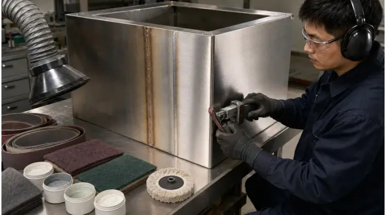
Uniformazione dei cordoni di saldatura e rimozione dei difetti
La rimozione di una saldatura o di una scanalatura profonda richiede un'asportazione controllata di materiale senza compromettere l'integrità strutturale del pezzo né le tolleranze dimensionali. Una sequenza standard di livellamento comprende:
- Rimuovere le scorie di saldatura, gli ossidi sciolti e gli spruzzi utilizzando una spazzola metallica dedicata in acciaio inossidabile.
- Livellare progressivamente il cordone di saldatura in rilievo utilizzando un abrasivo a grana grossa (ad esempio, un nastro ceramico a grana 80–120 o un disco abrasivo rigido).
- Ampliare l'area di lavoro per creare una transizione uniforme e graduale tra la zona di saldatura e il materiale di base.
- Utilizzare abrasivi sempre più fini per rimuovere i graffi profondi lasciati dalla fase di livellamento.
- Unire l'area riparata in modo che si armonizzi con la venatura o la lucentezza originali della superficie circostante.
Linee guida per gli operatori:
- Evitare una levigatura troppo aggressiva sulla lamiera sottile adiacente. Una rettifica eccessiva riduce lo spessore delle pareti al di sotto delle tolleranze accettabili, causando una compromissione della resistenza strutturale o il rifiuto immediato del pezzo durante il controllo qualità.
- Non modificare le dimensioni critiche del gambo della saldatura né lo spessore della gola definiti nel disegno tecnico.
- Mascherare o proteggere i fori adiacenti, gli inserti filettati, le superfici di tenuta e le quote di accoppiamento critiche.
- Quando si eliminano graffi profondi, è necessario levigare un’area più ampia. Cercare di levigare un graffio in una scanalatura stretta lascerà un’impronta visibile alla vista.
- In presenza di una forte colorazione da calore e di una spessa patina di ossido, potrebbe essere necessario ricorrere a un decapaggio chimico prima della levigatura meccanica.
- Le superfici estetiche visibili non devono presentare evidenti avvallamenti, segni di levigatura sfaccettati o spigoli eccessivamente arrotondati.
Finiture spazzolate e satinate
Il raggiungimento di una finitura spazzolata uniforme (n. 4) dipende in larga misura dalla tecnica e dalla costanza dell'operatore. Il controllo del processo deve tenere conto dei seguenti aspetti:
- Direzione e allineamento delle fibre.
- Larghezza del graffio e granulometria dell'abrasivo.
- Fusione delle sovrapposizioni tra i passaggi.
- Segni di avvio e arresto dell'utensile (segni di vibrazione).
- Coerenza visiva tra pannelli o gruppi adiacenti.
- Corrispondenza cromatica tra la zona riparata mediante saldatura e la lamiera originale.
I pannelli di grandi dimensioni a vista, di norma, non possono essere riparati localmente. Il tentativo di uniformare un piccolo difetto su una lastra spazzolata di grandi dimensioni spesso crea un effetto “a patchwork” visibile che riflette la luce in modo diverso. In questi casi, è necessario rifinire l’intera superficie a vista per garantire l’uniformità.
Per le finiture satinate, gli operatori utilizzano nastri abrasivi a grana fine, ruote in tessuto non tessuto o dischi per il trattamento delle superfici. È importante distinguere tra satinato direzionale e non direzionale. Per i complessi assemblaggi saldati con più piani intersecanti, una finitura satinata non direzionale (orbitale casuale) è spesso più facile da applicare e da mantenere in modo uniforme tra i lotti rispetto a una grana rigorosamente lineare.
Lucidatura a specchio e levigatura
La lucidatura a specchio è un processo articolato in più fasi. Saltare una fase o affrettare il procedimento comporterà la formazione di graffi microscopici intrappolati sotto una superficie altamente riflettente. Il processo si articola in tre fasi distinte:
- Levigatura fine: Utilizza grane progressive (fino a 600, 800 o 1200) per rimuovere tutti i segni di levigatura grossolani visibili e ottenere una superficie uniforme e piana.
- Lucidatura a taglio: Utilizza dischi rigidi (in sisal o cotone trattato) con una pasta abrasiva per rimuovere i micrograffi lasciati dalla levigatura fine e livellare ulteriormente la superficie.
- Lucidatura a colori: Utilizza dischi in cotone morbidi e a trama larga con un composto di finitura a grana fine per massimizzare la lucentezza e la nitidezza del riflesso.
In ogni fase è necessario utilizzare dischi di lucidatura dedicati e composti specifici. Il pezzo deve essere pulito accuratamente prima di passare alla fase successiva, per evitare che le particelle abrasive grossolane contaminino i dischi di lucidatura fini.
Le finiture a specchio modificano solo la riflettività superficiale; non correggono la geometria. La qualità visiva finale è fortemente limitata dalla planarità intrinseca del materiale grezzo, dalla distorsione da saldatura, dai segni lasciati dagli utensili CNC e dalle depressioni locali. Lucidare un pezzo di lamiera ondulata fino a ottenere una finitura a specchio produrrà semplicemente una superficie ondulata altamente riflettente, spesso definita «buccia d’arancia». Se non è possibile evitare l'uso di una superficie speculare di grandi dimensioni, i progettisti dovrebbero specificare un materiale di spessore maggiore (ad esempio, 2,0 mm o più) per resistere alla pressione esercitata durante la lucidatura e ridurre al minimo la distorsione visiva.
In che modo la pendenza, la geometria e il volume influenzano il processo
La sequenza di lucidatura non è universale. Le proprietà dei materiali, la geometria dei pezzi e il volume di produzione determinano quali metodi di finitura siano fisicamente possibili e commercialmente sostenibili.
Effetti del grado e della durezza
La composizione chimica e lo stato di trattamento termico dell'acciaio inossidabile influiscono direttamente sulla scelta dell'abrasivo e sulla generazione di calore.
- Gradi austenitici (304, 316): Questi materiali sono soggetti all'incrudimento. La rettifica locale ripetuta rende la superficie più difficile da lavorare. Presentano inoltre una scarsa conduttività termica, il che significa che il calore si accumula rapidamente nel punto di rettifica, aumentando il rischio di deformazioni e scolorimento.
- Gradi ferritici (430): Questi possono presentare strutture a grana di fabbrica originali più evidenti e variazioni di formatura, il che può richiedere una maggiore livellatura iniziale per ottenere una finitura estetica uniforme.
- Gradi martensitici (410, 420, 440C): La difficoltà di lucidatura varia in base alla durezza ottenuta con il trattamento termico. Mentre i pezzi ricotti si lavorano normalmente, i componenti martensitici temprati (ad esempio, 440C a 58+ HRC) resistono agli abrasivi standard a base di ossido di alluminio.
I componenti ad alta durezza richiedono spesso l'uso di abrasivi in ceramica, CBN (nitruro di boro cubico) o diamante per tagliare il materiale in modo efficiente senza generare calore eccessivo. È importante scegliere sempre il processo di lucidatura in base alla specifica qualità, allo stato di durezza e alla superficie di partenza, anziché trattare tutti gli acciai inossidabili della serie 400 allo stesso modo.
Caratteristiche interne e finitura in serie
La lucidatura manuale è limitata dall'accessibilità degli utensili. In caso di geometrie complesse o volumi di produzione elevati, si rendono necessarie tecnologie di finitura alternative.
| Parte o caratteristica | Processo adeguato | Limitazione principale |
| Angolo stretto o scanalatura corta | Cinghia piccola, ruota a alette o utensile rotante | Rischio di asportazione locale non uniforme del materiale |
| Piccoli componenti stampati/lavorati a macchina | Finitura a vibrazione o centrifuga | Non è possibile ottenere una grana direzionale controllata |
| Passaggio interno complesso | Lavorazione con flusso abrasivo (AFM) | Processo specializzato; relativamente costoso |
| Componente igienico-sanitario | Elettrolucidatura | Richiede una preparazione accurata e l'uso di bagni chimici |
| Ampio pannello visibile | Finitura superficiale con nastro largo o automatizzata | Planarità e uniformità della grana lungo i bordi |
| Assemblaggio complesso di piccoli volumi | Finitura manuale | Costi del lavoro più elevati e rischi legati alla coerenza |
La lavorazione ad abrasivo in flusso (AFM) è generalmente riservata come soluzione specializzata per cavità interne, quali canali di raffreddamento conformi o collettori aerospaziali, dove gli utensili fisici non possono arrivare. Per la produzione in serie di piccoli componenti, la finitura vibro-centrifuga e quella a massa sono i metodi standard per la sbavatura, l’arrotondamento degli spigoli e il miglioramento complessivo della superficie, riducendo significativamente il costo unitario rispetto alla lavorazione manuale.
DFM per l'accesso alla lucidatura
L'applicazione dei principi del Design for Manufacturing (DFM) sin dalle prime fasi della progettazione può ridurre drasticamente i costi di finitura superficiale e i tempi di consegna.
Raccomandazioni di progettazione:
- Lasciare uno spazio libero sufficiente affinché i nastri abrasivi, le ruote lucidanti e gli strumenti di ispezione possano raggiungere la superficie da trattare.
- Evitare fessure profonde e strette e angoli interni inaccessibili.
- Specificare raggi ampi per gli angoli interni, anziché angoli acuti di 90 gradi.
- Posizionare le saldature a vista in punti pianeggianti e facilmente accessibili, anziché all’interno di intersezioni strette.
- Ridurre al minimo le saldature non necessarie in prossimità delle zone designate come ad alta lucentezza o a effetto specchio, al fine di ridurre la deformazione termica.
- Distinguere chiaramente tra “facce visibili” e “facce non visibili” nel disegno 2D.
- Proteggere fori, filettature, superfici di tenuta e quote di accoppiamento con tolleranze strette dal contatto abrasivo.
- Mantenere intatta la pellicola protettiva in PVC applicata in fabbrica sulla materia prima durante le operazioni di punzonatura e piegatura, rimuovendola solo quando necessario.
Confronto dei costi dei processi di fabbricazione:
I produttori valutano generalmente tre opzioni per i gruppi di lamiera lavorata:
- Utilizzare lamiere pre-spazzolate/pre-lucidate e proteggerle durante la lavorazione.
- Saldare il materiale con finitura di fabbrica standard e ripristinare localmente la finitura solo nelle zone di saldatura.
- Saldare il gruppo e, successivamente, rifinire completamente l'intera unità.
I primi due metodi sono convenienti dal punto di vista economico, ma richiedono un posizionamento strategico delle saldature, una rigorosa protezione durante la lavorazione e una sapiente rifinitura locale. La terza soluzione (saldatura seguita da una rifinitura completa dell'intero pezzo) garantisce l'uniformità, ma può facilmente far aumentare il costo totale di produzione da 30% a 50% a causa dell'intenso lavoro manuale richiesto.
Ispezione delle superfici, rilavorazione e costo del lotto
Le indicazioni vaghe nei disegni sono la causa principale delle controversie con i fornitori e del rifiuto dei lotti. Il controllo qualità dell’acciaio inossidabile lucidato richiede una combinazione di misurazioni oggettive e standard visivi.
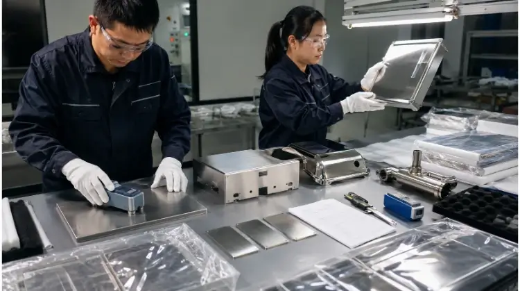
Annotazioni sui disegni e collaudo finale
Per garantire una qualità costante dei lotti, i disegni tecnici e gli ordini di acquisto devono definire chiaramente:
- Zone cosmetiche: Distinguere chiaramente tra “volti visibili” e “volti non visibili”.
- Direzione delle fibre: Specificare l'orientamento esatto delle finiture spazzolate (ad es., “Vena parallela al lato lungo”).
- Rugosità superficiale: Valori Ra o Rz di riferimento, se applicabili alla funzione.
- Criteri di accettazione: Numero massimo consentito di graffi, cavità o ondulazioni superficiali.
- Condizioni di ispezione: Distanza di visione, angolo e tipo di illuminazione standardizzati (ad esempio: “Osservato da una distanza di 24 pollici sotto luce fluorescente con un angolo di 45 gradi”).
- Campioni limite: Campioni fisici di riferimento approvati sia dall'acquirente che dal produttore.
Un profilometro che misura il valore Ra non è sufficiente per un’ispezione estetica completa. Il valore Ra non è in grado di descrivere la rettilineità delle venature, l’ondulazione della superficie, l’uniformità del colore o la nitidezza del riflesso speculare. Un campione di riferimento fisico, concordato di comune accordo, rimane lo standard più affidabile per l'accettazione dei prodotti cosmetici nella produzione di massa.
Difetti comuni nella lucidatura
Quando un componente non supera il controllo qualità, il tipo di difetto indica solitamente in modo diretto un’anomalia di processo. La seguente matrice di risoluzione dei problemi illustra gli errori più comuni nella lucidatura meccanica:
| Difetto | Probabile causa | Azione correttiva |
| Graffi incrociati | I residui di graniglia non sono stati rimossi completamente. | Tornare alla fase di levigatura precedente. |
| Segni a spirale | Ruota contaminata o movimento irregolare. | Pulire la superficie e ripetere la lucidatura finale. |
| Grana irregolare | Direzione incoerente o sovrapposizione. | Rifinire l'intera area visibile. |
| Lucentezza irregolare | L'area di riparazione è troppo piccola. | Frulla una superficie molto più ampia. |
| Alterazione del colore dovuta al calore | Pressione o tempo di permanenza eccessivi. | Abbassare la fiamma e rimuovere lo strato interessato. |
| Onde di superficie | Levigatura aggressiva su lamiera sottile. | Ridurre la pressione e ampliare l'area di contatto. |
| Macchie di ruggine | Contaminazione da acciaio al carbonio. | Rimuovere le impurità e valutare la passivazione. |
| Bordi arrotondati | Eccessiva asportazione di materiale a livello locale. Ciò è particolarmente importante nel caso di superfici di accoppiamento lavorate con macchine CNC o di profili di piegatura di lamiere di precisione, dove i bordi arrotondati possono compromettere le tolleranze di assemblaggio. | Proteggi i bordi e riduci la pressione di contatto. |
| Residuo composto | Pulizia insufficiente dopo la lucidatura. | Seguire la procedura di pulizia indicata. |
Coerenza dei lotti, protezione e costi
I costi di lucidatura non variano in modo lineare. Il prezzo finale per pezzo dipende dalla superficie visibile, dalla profondità dei difetti presenti nel materiale grezzo di partenza, dal numero e dalla posizione delle saldature e dall’accessibilità con gli utensili.
Analisi dei costi: Specificare in modo eccessivo un valore Ra basso o una finitura a specchio n. 8 aumenta in modo esponenziale le fasi di lavorazione, i tempi di ispezione e il tasso di scarti/rilavorazioni. Inoltre, se un pezzo è destinato alla verniciatura o all’incollaggio, una superficie eccessivamente liscia ridurrà notevolmente l’adesione del rivestimento. Specificare finiture ad alta lucentezza solo laddove siano richieste dal punto di vista funzionale o estetico.
La passivazione chimica dovrebbe essere specificata in base all'applicazione finale del prodotto, ai rischi di contaminazione e alla conformità alle norme specifiche del settore (ad esempio, ASTM A967), anziché essere considerata una fase automatica per tutti i componenti lucidati.
Infine, la finitura superficiale può essere facilmente danneggiata durante il trasporto. I pezzi finiti devono essere maneggiati con guanti puliti, protetti con una pellicola di mascheratura in PVC apposita e imballati con divisori non abrasivi per evitare l'attrito tra le parti metalliche durante la spedizione.
Conclusione
La lucidatura dell’acciaio inossidabile è un processo altamente controllato di ricostruzione fisica e chimica della superficie. Per ottenere una finitura omogenea è necessario abbinare la sequenza abrasiva corretta alle condizioni del materiale grezzo, gestire rigorosamente le sollecitazioni termiche durante la spianatura e stabilire criteri di ispezione chiari e basati su campioni prima dell’inizio della produzione.
Avete bisogno di una finitura uniforme, a spazzola, satinata, a specchio o a basso Ra per i vostri componenti in acciaio inossidabile lavorati? Inviate i vostri disegni, le specifiche dei materiali e i requisiti relativi alle superfici a vista a TZR. Il nostro team offre analisi dettagliate dei processi di produzione, strategie di finitura superficiale e preventivi competitivi per tutti i progetti di lavorazione CNC su misura e di lavorazione della lamiera, dalla prototipazione rapida alla produzione in serie.