
 English
 Spanish
 German
 Russian
 Italian
 French

Stainless steel 3D printing is an additive manufacturing process that builds metal components layer-by-layer using technologies like Laser Powder Bed Fusion (LPBF) or Binder Jetting. It is primarily used to manufacture complex geometries, conformal cooling channels, and consolidated assemblies that are impossible to produce via traditional CNC machining.
However, on the factory floor, printing the shape is only the first stage. A 3D-printed metal blank is rarely a finished product. The final mechanical strength, dimensional tolerances, and surface finish of your component are dictated entirely by your chosen printing route and the subsequent CNC machining and heat treatment operations.
To help you make a practical manufacturing decision, this guide covers what really happens on the shop floor. We will look at how 316L and 17-4PH perform in real applications. We will also look at the design changes you need to avoid warped prints.
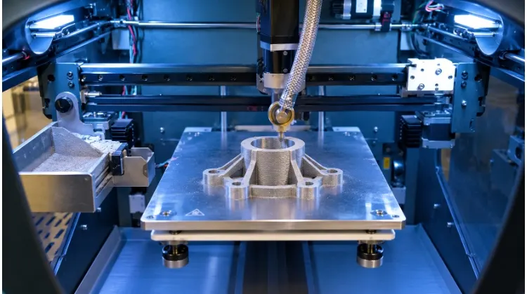
Compare the Main Stainless Steel Printing Processes
The term “metal 3D printing” covers several distinct technologies. Each handles the raw material and thermal cycles differently, which directly affects the final part’s density, cost structure, and design rules.
Laser Powder Bed Fusion (LPBF)
Often referred to as DMLS (Direct Metal Laser Sintering) or SLM (Selective Laser Melting), LPBF uses a high-power laser to selectively melt stainless steel powder in an inert gas environment.
The rapid melting and cooling cycle generates significant thermal stress. To prevent parts from warping or curling off the build plate, engineers must design rigid, sacrificial support structures. Additionally, because the part is built inside a bed of loose powder, any enclosed voids or internal cavities must feature designated exit holes to allow trapped powder to drain before heat treatment.
- Shop Floor Note: It is critical to distinguish a machine’s theoretical print resolution from the final part accuracy. LPBF creates near-fully dense metal, but the raw printed surface remains rough (typically Ra 5-15 µm). For bearing fits, sealing grooves, or precise mating surfaces, always add a machining allowance of 0.5 mm to 1.0 mm to the CAD model and plan for secondary CNC milling.
Binder Jetting
Instead of melting metal with a laser, binder jetting uses an area-wide printhead to deposit a liquid binding agent onto the powder bed, forming a fragile “green” part. This green part is then removed from the bed and placed in a high-temperature furnace to sinter the metal particles together.
During the printing phase, the surrounding powder supports the part, eliminating the need for printed support structures. However, during the furnace sintering phase, the metal softens as it nears its melting point, causing unsupported overhangs to sag under gravity. Custom ceramic setters are usually required in the furnace to prevent deformation.
- Shop Floor Note: Furnace sintering causes an isotropic linear shrinkage of roughly 16% to 20% (which equates to an over 40% volumetric reduction). While CAD software scales the model to compensate, uneven wall thicknesses will shrink at different rates, making tight tolerances difficult on large parts without secondary machining.
- Cost Scaling Mechanism: Because the printhead deposits binder across the entire bed in uniform passes, build time depends primarily on the Z-height rather than part count. Packing the build box densely (nesting) makes Binder Jetting significantly more cost-effective for batch runs than laser-based methods.
Bound Metal Extrusion
Similar to standard FDM plastic printing, bound metal extrusion builds parts using a polymer filament heavily loaded with stainless steel powder. Once printed, the green part undergoes a chemical or thermal debinding process to remove the polymer matrix, followed by furnace sintering to consolidate the metal.
This process requires you to evaluate the printer, the debinding station, and the furnace as a complete, interconnected system. The furnace capacity and debinding cycles often dictate your maximum part size and production throughput. While the final metal part usually retains slightly higher porosity and lower mechanical strength compared to LPBF parts, this method works very well for low-volume shop-floor tooling, assembly jigs, or early-stage functional prototypes.
Process Comparison Overview
| Process | Necessary Post-Processing | Dimensional Control | Surface Characteristics |
| LPBF | Stress relief, support removal, CNC machining. | High (typically ±0.1 to 0.2 mm before machining). | Rough, matte finish; visible melt pools. |
| Binder Jetting | Curing, sintering, minor machining. | Moderate (shrinkage affects consistency on large parts). | Slightly porous, smoother raw finish than LPBF. |
| Bound Metal Extrusion | Debinding, sintering. | Lower (prone to warping during debinding/sintering). | Visible layer lines, similar to plastic FDM. |
Decide Whether Your Part Should Be Printed
3D printing is not a universal replacement for conventional manufacturing. The decision to print a stainless steel part should rely on geometry, functional requirements, and supply chain constraints, rather than a general desire to use additive manufacturing.
Geometry and Tool Access
Printing offers the highest value when a part requires conformal cooling channels, complex fluid manifolds, or lattice structures that standard end mills and drills cannot reach. The alternative is usually split-machining—cutting the component into multiple manageable sections, machining them separately, and then welding or bolting them together.
However, complexity has practical limits on the shop floor. Even if an intricate cavity can be printed, you must verify that it can still be effectively cleaned of loose powder, post-machined if tolerances require it, and inspected for internal defects.
- Shop Floor Note: For internal channels, long blind holes are highly prone to trapped powder. Ensure fluid paths are continuous (through-holes) with exit diameters of at least 3 mm to allow for compressed air cleaning and powder recovery.
Part Consolidation
Consolidating multiple components into a single printed part reduces assembly labor, eliminates fasteners, and removes potential leak points at sealing joints. For instance, a complex hydraulic manifold with intersecting cross-drilled holes and plugs can be redesigned into a single optimized block with curved internal flow paths that reduce fluid pressure drops.
You must, however, consider the impact on maintenance and lifecycle costs. If a single native thread or wear surface on a consolidated manifold strips or gets damaged, the entire expensive assembly may need to be scrapped.
- Shop Floor Note: To mitigate this risk without sacrificing consolidation benefits, do not print unrepairable internal threads in high-wear zones. Instead, design those features as solid bosses, drill them post-print, and install stainless steel threaded inserts (such as Helicoils or Keenserts).
Alternative Manufacturing Routes
For simple brackets, flat enclosures, or thin-walled structures of uniform thickness, laser-cut and bent sheet metal remains significantly faster and more cost-effective. Solid metal blocks with straightforward features and straight holes are usually better suited for CNC milling or turning.
3D printing becomes the preferred route when traditional casting requires expensive tooling for a low-volume order, when casting lead times extend into several months, or when part weight reduction is a strict functional requirement. There is no universal complexity threshold or exact economic breakpoint—each project requires a dedicated cost and lead-time comparison based on the final delivery requirements.
Choose Materials for Strength and Corrosion Resistance
Selecting between 316L and 17-4PH is not a simple material swap. It requires balancing exposure to corrosive environments against mechanical yield requirements, secondary heat treatment obligations, and procurement verification standards.
316L Stainless Steel
316L is an austenitic chromium-nickel stainless steel modified with 2% to 3% molybdenum. The molybdenum content significantly enhances resistance to chloride pitting and crevice corrosion compared to standard 304 grades.
- Operating Environment and Temperature: 316L performs reliably in marine environments, food processing equipment, and chemical processing media. However, service temperatures between 425°C and 860°C can induce chromium carbide precipitation along grain boundaries, potentially compromising corrosion resistance unless low-carbon specs are strictly maintained.
- Surface Condition Impact: The as-printed surface of an LPBF 316L component (typically Ra 5–15 µm) contains micro-crevices that trap contaminants and accelerate localized pitting. For critical chemical or marine exposure, as-printed parts must undergo electropolishing or chemical passivation (per ASTM A967) to match the passive oxide layer performance of cold-drawn bar stock.
- Material vs. Compliance: Printing with 316L powder does not automatically make a part suitable for medical or pharmaceutical use. Compliance standards (such as ASTM F3184 for additive manufacturing) require strict powder lot traceability, inert gas batch logs, documented internal porosity limits, and density testing (via Archimedes’ method) on co-printed witness coupons.
17-4PH Stainless Steel
17-4PH (AISI 630 / UNS S17400) is a martensitic, precipitation-hardening stainless steel. It is selected for high-stress structural components, turbine impellers, and wear-resistant tooling.
- As-Printed vs. Heat-Treated State: In its as-printed condition, 17-4PH typically contains a non-equilibrium mixture of metastable austenite and martensite with high internal stress. In this state, its mechanical properties are erratic and unsuited for service.
- Standard Heat Treatment Conditions:
- Condition A (Solution Annealed, ~1040°C): Resets the microstructure to homogeneous martensite. This is the required intermediate state prior to precipitation hardening.
- Condition H900 (~480°C aging): Produces peak yield strength (often exceeding 1000 MPa) and maximum hardness (~40–44 HRC), at the expense of lower impact toughness and reduced elongation.
- Condition H1150 (~620°C aging): Over-ages the precipitates, lowering the yield strength (~750–850 MPa) while significantly improving fracture toughness, elongation, and resistance to stress corrosion cracking (SCC).
- Shop Floor Note (Dimensional Shift): Aging from Condition A to H900 causes a predictable dimensional contraction of approximately 0.04% to 0.06%. When planning secondary CNC operations, manufacturing engineers must decide whether to machine in the softer Condition A state and calculate for shrinkage, or machine post-H900 to guarantee final tolerances at the expense of much higher cutting tool wear.
Strength and Fatigue
Static mechanical properties published on machine vendor data sheets represent optimal, unidirectional tensile test bars. Real-world dynamic performance deviates significantly from these figures.
- Static Yield vs. Fatigue Endurance: Due to the extremely rapid solidification rates of the laser melt pool, as-printed LPBF stainless steels have very fine grain structures. Their static tensile yield strengths often match or exceed those of annealed wrought bar stock. However, high-cycle fatigue strength is typically 30% to 50% lower than wrought stock under identical cyclic load conditions.
- Defect Sensitivity and Build Direction: In dynamic applications, fatigue failures initiate at microscopic stress concentrations. In additive stainless steel, these sites are sub-surface lack-of-fusion (LoF) voids, residual gas pores, or inter-layer boundaries. Consequently, ductility and fatigue resistance along the Z-axis (parallel to the build direction) are typically 10% to 25% lower than along the XY-plane.
- Defect Remediation and Real Costs: For cyclically loaded components, you can specify Hot Isostatic Pressing (HIP) at ~1150°C and 100+ MPa to consolidate internal micro-porosity. However, procurement teams should note that HIP is a premium batch process that adds significant cost and several days to the lead time.
- Surface Micro-notches: Internal HIP consolidation is useless if the exterior remains rough; the as-printed surface acts as a continuous field of micro-notches. For true fatigue resistance, critical load-bearing radii must be CNC machined or deeply polished to eliminate surface crack initiators.
Design Parts to Reduce Printing and Cleaning Problems
Design for Additive Manufacturing (DfAM) for stainless steel is not about creating organic shapes for visual appeal. Its primary role on the factory floor is controlling weld shrinkage forces, avoiding manual grinding labor, and ensuring that loose powder can be completely cleared before heat treatment.
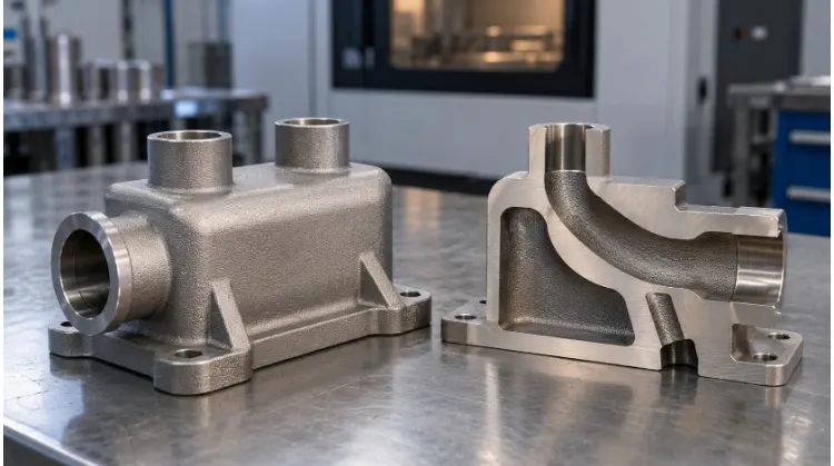
Orientation and Supports
The orientation of the part on the build plate governs build time, support contact points, and the surface finish of critical features.
- The 45-Degree Threshold: Downward-facing surfaces (overhangs) angled flatter than 45° relative to the horizontal build plate cannot dissipate heat effectively into the loose powder. This creates melt-pool sag and requires solid anchor supports.
- The Cost of Support Removal: Every support structure must eventually be removed mechanically using pliers, end mills, or wire EDM. In poorly optimized designs, manual support removal and surface blending can account for 20% to 30% of the total part manufacturing cost.
- Accessibility: Never position support structures inside narrow channels, blind pockets, or near sensitive O-ring gland faces where cutting tools cannot reach.
- Self-Supporting Design Modifications: Replace horizontal overhangs with 45° chamfers. For horizontal internal passages with diameters over 8 mm, replace round cross-sections with teardrop or diamond geometries. The pointed ceiling of a teardrop is self-supporting, eliminating the need for internal supports.
Walls and Distortion
Stainless steel has relatively low thermal conductivity and a high thermal expansion coefficient, making it vulnerable to distortion during printing and subsequent thermal processing.
- Thermal Stress and Cross-Sectional Jumps: In LPBF, sudden transitions between massive solid blocks and thin wall sections (e.g., a 1 mm fin directly attached to a 30 mm baseplate) concentrate thermal strain at the interface. As the part cools, this stress can cause the part to rip free from its supports or bow severely when cut from the build plate.
- Process-Specific Distortion Mechanisms:
- LPBF Distortion: Driven by localized residual thermal strain during melting. Heavy support anchoring and generous transition fillets (radius ≥ 3.0 mm) are required to distribute these stresses.
- Sintering Distortion (Binder Jetting / FDM): Driven by gravity and differential shrinkage. Thick walls retain heat and shrink at different rates than thin ribs, causing broad flat plates to saddle or dish in the furnace.
- Wall Thickness Guidelines: For LPBF, keep structural walls between 1.0 mm and 5.0 mm. Unsupported walls thinner than 0.8 mm tend to buckle under the mechanical drag of the powder recoater blade. For sintering processes, maintain uniform nominal walls between 1.5 mm and 4.0 mm across the entire part to promote uniform shrinkage.
Channels and Access
A complex manifold is unusable if loose metal powder remains welded or trapped inside the internal circuits during the first furnace cycle.
- Flow-Through Depowdering Requirements: Unmelted 316L and 17-4PH powder is heavy and packs tightly. Blind internal passages cannot be reliably purged with compressed air. Every internal cavity must have at least two access ports—an inlet and an outlet—measuring at least 3.0 mm in diameter.
- Pre-Heat Treatment De-Caking: Powder evacuation must occur before high-temperature stress relief. If a part enters a 650°C–1000°C furnace with trapped powder inside, the particles will lightly sinter to the channel walls, forming a rough, abrasive crust that will continually shed into fluid systems during service.
- Datum and Clamping Surfaces for CNC: Never design an organic, fully curved exterior if critical bores or threads require secondary CNC machining. The machinist needs rigid, parallel clamping surfaces to fixture the part securely in a vise. Design sacrificial clamping lugs or flat datum pads into the raw print, which can be easily faced off in the final milling operation.
Plan Post-Processing for Fit and Surface Quality
Printing simply yields a raw metal blank. Meeting the final engineering drawing requirements for mechanical fit, surface finish, and dynamic strength relies heavily on secondary post-processing operations.
Heat Treatment
Thermal processing in metal 3D printing serves multiple distinct purposes. The required sequence depends directly on the chosen printing technology and the target material properties.
- Stress Relief (Process Requirement): For LPBF, the part must be stress-relieved in a furnace while it is still welded to the steel build plate. Skipping this step and cutting the part off immediately will cause the residual thermal stresses to violently warp or crack the component.
- Solution Annealing & Sintering: In binder jetting or bound metal extrusion, sintering fuses the metal powder at temperatures near melting. For LPBF 17-4PH, solution annealing (Condition A) resets the microstructure to a uniform state before further hardening.
- Aging / Precipitation Hardening (Performance Target): Applied specifically to 17-4PH (e.g., Condition H900 or H1150) to reach the target yield strength and hardness. This is dictated by the part’s final load requirements, not the printing process itself.
- Hot Isostatic Pressing (HIP): An optional, premium process that applies high heat and uniform gas pressure to collapse internal micro-voids. HIP is selected solely to improve high-cycle fatigue life and impact toughness.
Precision Machining
A raw 3D printed surface cannot achieve the geometric tolerances (GD&T) required for dynamic assemblies, bearing press-fits, or fluid sealing. You must clearly separate the rough separation steps from precision finishing.
- Substrate Separation and Roughing: LPBF parts are typically separated from the steel build plate using a bandsaw or wire EDM. Support structures are then removed using pliers, chisels, or rough milling.
- Functional Feature Machining: Dowel pin holes, tapped threads, and O-ring grooves must be finished on a CNC mill or lathe. To ensure the machinist can achieve the required tolerances, the CAD model sent for printing must include 0.5 mm to 1.0 mm of machining allowance on all critical surfaces.
- Shop Floor Note (Workholding): Machining complex, organically shaped 3D printed parts is notoriously difficult because they lack flat, parallel clamping surfaces. Top-tier manufacturers mitigate this by 3D printing custom polymer conformal soft jaws to securely hold the organic metal shapes in standard CNC vises without crushing thin walls.
Surface Treatment
The as-printed LPBF surface resembles a rough sand casting (Ra 5–15 µm). Surface treatments are chosen based on aesthetics, corrosion resistance, or mechanical fatigue needs.
- Media Blasting: Bead or sandblasting removes light oxidation and creates a uniform matte finish. It is primarily cosmetic.
- Shot Peening: Bombarding the surface with hard spherical media induces a layer of compressive residual stress. This closes surface micro-cracks and significantly improves fatigue resistance.
- Passivation and Electropolishing: For 316L used in medical or marine environments, the rough printed surface must be leveled and chemically cleaned. Electropolishing removes the microscopic peaks that trap corrosive agents, while passivation (per ASTM A967) restores the protective chromium oxide layer.
- Internal Access Limits: Standard polishing methods only work on line-of-sight exterior surfaces. Smoothing complex internal conformal cooling channels requires Abrasive Flow Machining (AFM), which adds significant cost and lead time.
Verify Quality Against the Part’s Actual Requirements
High relative density (e.g., 99.5%) does not automatically mean a part is free of critical defects. Quality assurance for 3D printed stainless steel requires matching the inspection method to the specific structural risks.
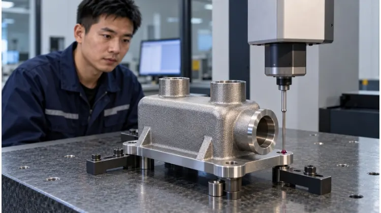
Dimensions and Assembly
Dimensional inspection must occur after all thermal treatments and CNC machining, as stress relief, aging, and sintering shrinkage will predictably alter the raw printed geometry. Use a Coordinate Measuring Machine (CMM) to verify critical GD&T features like flatness on sealing faces and concentricity on bearing bores. For manifolds or consolidated parts designed to replace multiple sub-components, physical assembly tests with the actual mating hardware are often the most reliable way to confirm practical fit.
Internal Quality
Additive manufacturing can introduce unique internal flaws, including lack-of-fusion (LoF) voids, trapped shielding gas pores, or unfused powder caked inside blind channels.
- Inspection Methods & The Cost Trap: Standard ultrasonic testing is often ineffective due to the rough surface and complex geometries of 3D printed parts. For critical aerospace or pressure-retaining components, Industrial CT (Computed Tomography) scanning is used to verify internal channel clearance and map void distribution. However, procurement teams should be warned: Industrial CT scanning is expensive and can easily double the unit cost of a part. Unless required by strict safety compliance, it is far more cost-effective to rely on strict machine process controls, destructive testing of the First Article, and co-printed witness coupons for production validation.
- Expectation Management: Do not assume a part is flawless. A 99.5% density specification still leaves 0.5% room for micro-defects. Specify where porosity is strictly prohibited (e.g., near sealing walls) rather than demanding zero porosity throughout the entire bulk volume.
Functional Testing
Material data sheets prove the capability of the raw powder, not the performance of your specific part.
- Tensile Testing: If mechanical strength is critical, request that the supplier prints standard tensile witness coupons on the same build plate as your parts. Testing these coupons verifies the success of the printing and heat treatment parameters for that specific batch.
- Pressure and Leak Validation: For manifolds and fluid-handling parts, hydrostatic pressure testing or helium leak testing is mandatory to ensure thin internal walls are fully dense and not weeping fluid through micro-pores.
Quality Verification Reference
| Part Requirement | Verification Method | Standard Delivery Record |
| Material Composition | OES / Spectrometry on powder | Powder Mill Certificate (CoC) |
| Mechanical Strength | Tensile test on co-printed coupons | Mechanical Test Report (Yield, UTS, Elongation) |
| Dimensional Accuracy | CMM / Optical Scanning | First Article Inspection (FAI) Report |
| Internal Void / Powder Check | Industrial CT Scan / X-Ray | CT Scan Radiography Report |
| Fluid Containment | Hydrostatic or Helium Leak Test | Pressure Test Certificate |
Ready to Quote Your Next Project?
At TZR, we understand that manufacturing decisions are driven by cost, strict tolerances, and realistic lead times. Whether your project is best suited for metal 3D printing, precision CNC machining, or custom sheet metal fabrication, our engineering team can evaluate your files and recommend the most reliable and economical manufacturing route.
Submit your drawings to TZR today to review your design for manufacturability and get a direct cost and lead-time comparison for your metal components.