
 English
  Spanish
  German
  Russian
  Italian
  French
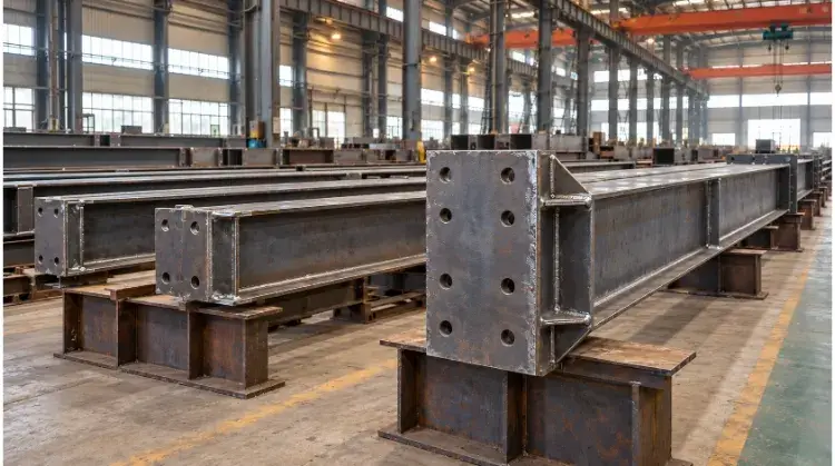
Structural steel fabrication is the industrial process of cutting, bending, and welding standard raw steel into specific load-bearing components. This process transforms raw materials into ready-to-assemble frames for commercial buildings, industrial equipment, and infrastructure projects.
For procurement managers and structural engineers, a successful fabrication project is measured by three strict metrics: precise hole alignment to prevent site delays, verified weld quality, and predictable delivered costs. A poorly managed shop floor doesn’t just waste steel; it burns through your field labor budget.
That’s why the fabrication stage is so critical. It’s not just about cutting and welding heavy metal; it’s about controlling the dimensions and quality in the shop so the field erection actually goes smoothly.
What Does Structural Steel Fabrication Include?
It is helpful to distinguish between steel production and steel fabrication. Steel production happens at a mill, where raw materials are processed into standard stock lengths (like raw H-beams or flat plates). Fabrication is the secondary process where a machine shop cuts, drills, bends, and welds those standard profiles to match a specific engineering blueprint.
Common Structural Components
Rather than just a list of parts, it is better to look at how components interact within a standard rigid frame:
- Columns: Provide vertical support, transferring roof and floor loads down to the foundation.
- Beams: Horizontal members that carry floor or roof loads across spans.
- Bracings: Diagonal members installed to resist lateral forces like wind or seismic activity.
- Base Plates & Connection Plates: The critical joining elements. A heavy base plate is welded to the bottom of a column for foundation anchoring, while connection plates (such as shear tabs or gusset plates) are welded to the column flanges so beams can be bolted into place on-site.
Shop Fabrication and Site Assembly
Fabrication yields different levels of completion depending on transport limits and project design:
- Single Parts: Basic items like a cut beam with drilled holes.
- Welded Assemblies: A completed section, such as a column with its base plate, lifting lugs, and connection tabs already welded in place.
- Pre-Assembled Modules: Multi-part frames bolted or welded together in the shop before shipping.
Business Impact: The primary goal of shop fabrication is to complete as much complex work as possible in a controlled environment. Shop welding is highly controlled, easier to inspect, and significantly cheaper per hour than field welding. Site assembly should ideally be reserved for bolting prepared components together, keeping expensive field labor and crane rental times to an absolute minimum.
What to Check Before Steel Fabrication Starts?
Proceeding without verified specifications often leads to incorrect material procurement and shop rework. Several technical details must be locked in before the first cut is made.
Approved Drawings
Production should only begin using final “Issued for Construction” (IFC) or formally approved shop drawings. Fabricators need to verify revision numbers, critical dimensions, and specific connection details.
- Responsibility Boundary: The structural engineer dictates the load and structural design; the fabricator translates that design into precise shop drawings for manufacturing. Fabricators cannot fix structural design flaws.
- Pro Tip: While 3D modeling and clash detection software (like Tekla) are standard for finding physical interferences, they are not a substitute for quality engineering. The output is only as reliable as the input data provided.
Material Grades and Sections
The shop must confirm exact material grades (e.g., ASTM A992 for structural shapes, ASTM A36 for plates), section profiles, thicknesses, and supply conditions.
- The Pitfall of Substitution: If a specified section size or grade is out of stock, any proposed substitution must be formally submitted to the design engineer for approval. Fabricators should never substitute materials independently just because an alternative looks similar or has a comparable yield strength. A plate with a different carbon equivalent can lead to severe weld cracking or failed NDT (Non-Destructive Testing) inspections down the line.
Acceptance Requirements
Project specifications for inspection and acceptance must be agreed upon early and documented clearly.
- Dimensional Tolerances: What is the acceptable deviation for hole alignment or beam camber?
- Weld Criteria: Specify the exact standard (such as AWS D1.1 or EN 1090).
- NDT Scope: Specify which welds require visual inspection (VT) versus ultrasonic testing (UT) or radiographic testing (RT).
Cost Driver: Always align these technical requirements with the initial quote. Asking a fabricator for 100% ultrasonic weld testing at the end of a project, when the initial quote only factored in standard visual inspections, will immediately trigger heavy additional charges and schedule delays.
How the Structural Steel Fabrication Process Works?
Transforming raw steel into a load-bearing component is not about having the most “advanced” equipment on the floor; it is about choosing the exact right process for the material thickness, structural purpose, and project budget.
Material Preparation and Cutting
Before a blade ever touches the steel, the shop must verify the material’s heat numbers and transfer traceability markings. Losing a heat number during cutting means losing the material’s certification—which instantly turns structural steel into scrap.
When cutting standard profiles or plates to size, the method must match the material form, thickness, required edge quality, and volume:
- Sawing (Cold saws / Band saws): The standard, cost-effective choice for cutting heavy H-beams, tubes, and angles to length. It leaves a clean, cold edge without heat-affected zones.
- Oxy-Fuel Cutting: The workhorse for extremely thick carbon steel (e.g., heavy base plates over 2 inches). It is slower and leaves a wider kerf, but handles thicknesses other methods cannot.
- Plasma Cutting: Highly efficient for medium-thickness plates. It offers an excellent balance of speed and edge quality for gussets and connection plates.
- Laser Cutting: Best for thinner plates requiring tight tolerances and clean edges.
Cost & Lead Time Driver: Do not over-specify cutting requirements. Specifying laser cutting for a 2-inch base plate that will ultimately be buried in concrete is not only a waste of your budget—it creates unnecessary bottlenecks on the shop floor, delaying your entire delivery.
Hole Making and Forming
Processes here serve two different functions: preparing connections and shaping the component.
- Hole Making: Holes for bolted connections are typically created on CNC drill lines. While punching is faster and cheaper, it should generally be restricted to thinner materials. Punching thick steel can induce micro-fractures around the hole edges—a critical weak point that might pass visual inspection but fail under dynamic field loads. Most heavy structural connections require drilled holes.
- Beveling: If a joint requires a full-penetration weld, the plate edges must be beveled (angled) mechanically or via thermal cutting to allow the weld metal to reach the root of the joint.
- Forming (Bending/Rolling): When architectural designs require curved beams or rolled plates, heavy hydraulic presses or plate rollers are used. This process must be carefully controlled so it does not stretch the steel beyond its tensile limits.
Fit-Up and Welding
A perfect weld on a bad fit-up is just a perfectly welded piece of scrap. Fit-up (tacking the pieces together) and welding are where the component actually takes shape. This phase requires strict adherence to approved procedures rather than relying solely on a welder’s personal experience.
Every weld must follow a WPS (Welding Procedure Specification), which dictates the exact voltage, wire feed speed, shielding gas, and travel speed. Welders must hold valid certifications for the specific position and process (e.g., FCAW, SMAW) dictated by the WPS.
To understand shop floor control during this phase, here is a summary of the critical steps:
| Process Stage | Purpose | Inspection & QC Focus |
| Fit-Up & Tacking | Temporarily hold parts in the exact position before final welding. | Dimensional check, joint gap, root face, and overall alignment. |
| Root Weld Pass | Fuses the deepest part of a full-penetration joint. | Slag removal, penetration depth, absence of root cracks. |
| Fill & Cap Passes | Builds the weld to required volume and seals the joint. | Interpass temperature control, visual appearance, weld size (leg length). |
| Final Assembly | Verifies the completed welded component against shop drawings. | Overall length, sweep/camber, twisting, and NDT (UT/RT) if specified. |
How to Prevent Fit-Up Problems on Site?
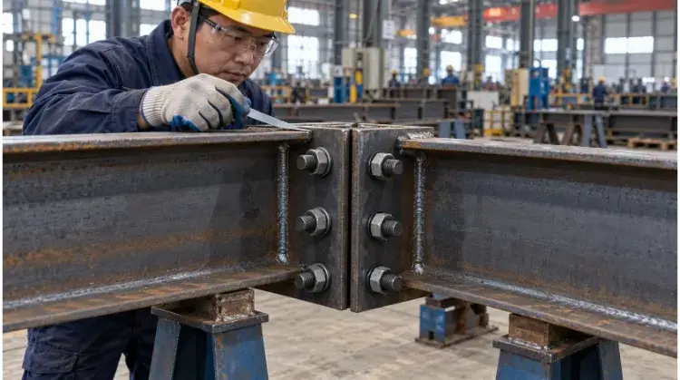
A fabricated beam is completely useless if it cannot be bolted to its column on-site. When steel does not fit, the erection crew is forced to ream holes, flame-cut adjustments, or force pieces together in the air—halting crane operations and burning expensive field labor hours.
Hole and Plate Alignment
Site fit-up issues usually stem from a misunderstanding of how dimensional variations stack up. You cannot apply a single, blanket tolerance to an entire 40-foot beam.
- Cumulative Tolerance: Shops must measure hole patterns from a fixed center datum point. If a fabricator measures the first hole from the edge of the beam, and the next hole from the previous one, the tiny deviations compound. By the time they reach the other end of a 40-foot beam, the bolt holes may be a quarter-inch off, making field connection impossible.
- End Plates and Base Plates: These must be checked strictly for squareness. A base plate welded just 1 degree off perpendicular will cause a tall column to lean significantly out of plumb at the top.
Weld Distortion Control
Heat is the enemy of straight steel. When a heavy weld cools, it shrinks. This thermal contraction can pull heavy steel beams out of alignment, causing twisting, bowing, or warping.
- Mitigation Techniques: Quality shops do not just weld continuously until the joint is filled. They use weld sequencing (welding on alternating sides to balance the heat pull), heavy physical clamping, and continuous in-process measurements.
- Business Impact: If a beam with a warped connection plate is shipped to the site, the erection crew will struggle to seat it. Forcing a warped connection together with high-strength bolts introduces dangerous residual stresses into the frame before the building even takes a structural load.
Trial Assembly and Match Marks
For standard grid buildings, CNC accuracy is usually enough—paying for full shop trial assembly here is a waste of your money. But for complex geometric structures (like stadium trusses or non-right-angle pipe nodes), the shop should perform a trial assembly (shop laydown) before shipping.
- Match Marking: During trial assembly, components are bolted together in the shop yard to verify fit. The connecting parts are then stamped or painted with unique “match marks” (e.g., Node A1 connects to Beam A1).
- Field Benefit: This serves as a foolproof assembly guide for the site crew, ensuring that the exact pieces that fit perfectly in the shop are paired together in the field.
Example Case (The Value of Trial Assembly):
Scenario: A fabricator is tasked with building a 60-foot clear-span roof truss made of three bolted sections.
Shop Action: Instead of shipping the three sections directly to the site, they are laid out horizontally in the shop yard.
Discovery: The trial assembly reveals that weld shrinkage on the middle chord caused the final bolt holes on the right section to misalign by 3/8 inch.
Resolution: The shop reams and adjusts the holes on the ground using shop equipment, fully resolves the alignment, and applies match marks.
Result: The truss sections are erected on-site in one day with zero crane delays. Had this 3/8-inch deviation been discovered in the air, it would have resulted in days of costly field modifications and structural engineer RFIs.
How to Protect and Inspect Fabricated Steel?
Previous sections focused on preventing errors during manufacturing; this phase is about verifying final quality and ensuring the steel survives its intended operating environment—and the journey to get there.
Surface Preparation and Protection
Bare carbon steel rusts rapidly when exposed to moisture. Choosing between industrial paint systems and Hot-Dip Galvanizing (HDG) depends on the operating environment, component design, and future maintenance plans.
- The Golden Rule of Coatings: Applying expensive marine-grade paint over mill scale or rust is a complete waste of money. Surface preparation accounts for 80% of a coating’s success. Quality fabricators will shot-blast steel to a recognized standard (such as ISO 8501-1 SA 2.5) to create a clean, rough profile that the primer can actually adhere to.
- Painting vs. Galvanizing: Multi-coat paint systems (zinc-rich primers with epoxy/polyurethane topcoats) are highly customizable and easy to touch up on-site. HDG submerges the steel in molten zinc, providing exceptional internal and external corrosion resistance for hollow sections. However, HDG can cause thermal distortion in thin plates and requires engineered drain holes in the design.
- A Note on Fireproofing: Intumescent coatings are often applied to structural steel. It is critical to remember that fireproofing solves a thermal structural problem, not a corrosion problem. It must be applied over a compatible anti-corrosion primer.
Dimensions and Weld Quality
Before the steel leaves the shop, it must undergo a final sign-off. “Strict quality control” is a marketing buzzword; procurement teams need to know exactly what is being verified.
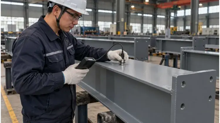
- Dimensional Checks: Inspectors verify overall length, sweep, camber, and critical connection-point coordinates against the IFC drawings.
- Weld Verification: 100% of structural welds require Visual Testing (VT) to check for surface defects like undercut or porosity.
- The Cost of NDT: Non-Destructive Testing (UT for internal cracks, RT for volumetric flaws) is expensive. You must clearly define the NDT scope in your initial RFQ (e.g., “10% UT on all full-penetration welds”). Demanding arbitrary NDT increases late in the project will instantly disrupt your schedule and budget.
Traceability and Inspection Records
When the steel arrives on-site, the accompanying paperwork is just as important as the metal itself. If the building inspector or your final client asks for proof of compliance, you cannot rely on verbal assurances. Your handover package should contain Material Test Reports (MTRs), signed NDT reports, and Dry Film Thickness (DFT) gauge readings.
For International Procurement: Paper reports are not always enough. Top-tier export fabricators provide pre-shipment video verification of critical dimensions and trial assemblies before the steel is ever loaded into a shipping container. Once your structural steel crosses the ocean, it is entirely too late to fix a misaligned bolt hole.
What Affects Structural Steel Fabrication Cost?
Many procurement managers mistakenly believe that steel fabrication is priced strictly by weight (cost per ton). In reality, fabricators quote based on material utilization and total shop hours.
Material Use and Availability
Standard structural profiles (like W-shapes or standard hollow sections) are heavily commoditized. If your engineering team specifies a highly unusual section size, the fabricator may have to order a massive minimum mill quantity, and you will pay for the scrap.
- Cost Driver: Whenever the design allows, stick to readily available regional stock sizes. Standardizing your steel sections dramatically reduces material lead times and raw material waste.
Part Count and Weld Details (Design for Manufacturing)
Every time a steel piece is moved, clamped, drilled, or welded, the labor meter is running. You can work with your fabricator to reduce costs through smart DFM (Design for Manufacturing) adjustments that maintain structural integrity:
- Standardize Hole Sizes: If a beam has 3/4-inch, 7/8-inch, and 1-inch holes, the CNC drill line must stop to change tools multiple times. Standardizing to a single bolt size across the project saves significant machining time.
- Reduce Part Count: Consolidating multiple small stiffener plates into a single, thicker, smarter plate reduces cutting, fit-up, and welding time.
- Weld Accessibility: A joint that is difficult for a welder to reach takes twice as long to weld and is far more likely to fail inspection.
Finishing and Delivery Costs
When comparing quotes from different fabricators, check the exclusions. The lowest base price often hides aggressive upcharges for logistics and final processing.
- Logistics Volume & Container Optimization: For global sourcing, shipping empty space is a budget killer. A smart fabricator will work with your engineers to design splices and boltings that allow large trusses to be broken down and optimized for standard 40ft HQ shipping containers. Furthermore, packaging must account for ocean transit—bare steel needs heavy-duty marine rust inhibitors if it is spending four weeks at sea.
- Quote Validity: Steel prices fluctuate based on global iron ore and scrap markets. Fabricator quotes are typically only valid for 7 to 14 days. Do not build a 6-month project budget on an expired steel quote.
Don’t let unoptimized designs inflate your manufacturing and shipping costs.
Send us your 3D CAD models or IFC drawings today. Our engineering team will perform a Free DFM & Cost-Reduction Review to identify specific cost-saving opportunities, container-packing optimizations, and provide a clear, transparent quote.