
 English
 Spanish
 German
 Russian
 Italian
 French

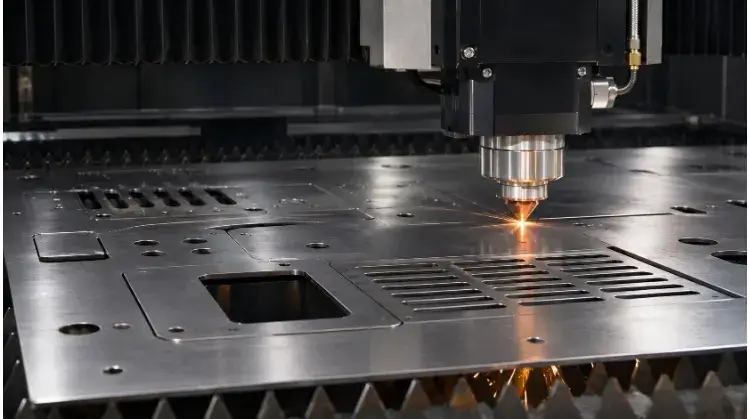
Sheet metal laser cutting is a thermal manufacturing process that uses a CNC-guided laser beam to melt and pierce flat metal sheets. Assisted by nitrogen or oxygen gas, it delivers high-precision profiles, tight tolerances, and scalable blanking for carbon steel, stainless steel, and aluminum components.
Many engineers assume a high-power laser cutter can perfectly replicate any 2D CAD file. In reality, ignoring material thermal behaviors, minimum feature ratios, and edge conditions often leads to warped cutouts, expensive secondary machining, or total assembly failures on the shop floor.
Use the quick reference table below to determine which aspects of your part require specific verification before requesting a quote:
| Part Requirement | What to Verify Before Quoting |
| General profiles and mounting holes | Exact material grade, thickness, and standard tolerances |
| Small holes, narrow slots, and dense cutouts | Feature-to-thickness ratio capability, thermal distortion risks |
| Precision fits or locating holes | Finished tolerances vs. need for secondary machining (drilling/reaming) |
| Bent or welded assemblies | Bend reliefs, safe hole distances, and who calculates the flat pattern |
| Cosmetic surfaces and painted parts | Deburring scope, edge oxide removal, and surface protection |
Match Materials and Thickness to Cutting Requirements
Different alloys behave differently under a laser beam. The choice of material affects not only structural strength and corrosion resistance but also exactly how the part cuts, forms, and what post-processing it will mandate.
Material Grades
Carbon steel, stainless steel, and aluminum represent the majority of laser-cut parts. When specifying materials, call out exact grades rather than general categories (e.g., “Aluminum” or “Stainless”). Processing behaviors, particularly regarding localized heating and subsequent bending, vary significantly within the same material family.
For highly reflective metals like copper and brass, verify that your supplier operates high-power fiber lasers designed to prevent back-reflection from damaging the machine optics.
| Material Grade | Why Choose It | Typical Parts | Processing Notes & Risks |
| Carbon Steel (e.g., SPCC, Q235, A36) | Cost-effective, high strength, easy to weld. | Enclosures, brackets, structural frames. | Risk: Edge oxide scale from oxygen cutting must be mechanically removed before powder coating, otherwise the paint will peel. |
| Stainless Steel (e.g., 304, 316L) | High corrosion resistance, good aesthetics without plating. | Medical device panels, food-grade equipment. | Note: Usually cut with nitrogen to maintain a clean, oxide-free edge, though this increases the hourly machine rate. |
| Aluminum (e.g., 5052, 6061) | Lightweight, good strength-to-weight ratio. | Aerospace components, electronic housings. | Risk: 6061 is prone to cracking during tight bends; specify 5052 if complex forming is required. |
| Copper / Brass (e.g., C110, C260) | Excellent electrical and thermal conductivity. | Busbars, electrical contacts, heat sinks. | Note: Requires specialized fiber lasers. Maximum stable cutting thickness is generally lower than that of steel. |
Thickness Capability
Machine power ratings (e.g., 6kW, 12kW) indicate the maximum thickness a laser can pierce, but this does not equal the stable, economical production range for all geometries. Pushing a machine to its absolute maximum thickness often results in heavy edge striations (vertical grooves), excessive dross, or wider kerf variations from the top of the cut to the bottom.
Thickness capability must be evaluated alongside the part’s specific features. For parts near the upper thickness limit of a facility’s equipment, or those containing dense intricate details, it is highly recommended to request a first article inspection to confirm edge quality is acceptable for your application.
Assist Gas
Assist gases clear molten metal from the cut and dictate the chemical condition of the edge. This directly impacts downstream costs like mechanical cleaning, welding prep, and finishing.
- Oxygen: Typically used for carbon steel. It creates an exothermic reaction that speeds up the cut but leaves a dark oxide layer (scale) on the edge. This layer usually needs to be sanded or tumbled off before powder coating or welding, which adds manual labor costs to your invoice.
- Nitrogen: Commonly used for stainless steel and aluminum. It shields the cut from ambient oxygen, resulting in a clean, bright, and oxide-free edge. While nitrogen processing has a higher hourly cost due to heavy gas consumption, it often saves money overall by eliminating the need for secondary edge cleaning.
- Compressed Air: A cost-effective alternative for thinner materials. It leaves a slightly rougher or discolored edge, making it suitable for internal structural components where cosmetics and paint adhesion are not critical.
Design Features That Cut and Assemble Reliably
Design intent and manufacturing reality often diverge around small features. Understanding how a high-power laser interacts with localized geometry helps prevent defects, scrap, and expensive secondary operations.
Holes and Slots
Small features are highly susceptible to thermal blowout. A standard manufacturing guideline is that hole diameters and slot widths should be equal to or greater than the material thickness (a 1:1 ratio). Cutting a 2mm hole in 3mm thick steel, for example, risks melting the surrounding material, resulting in a tapered or non-cylindrical hole.
If a precision press-fit or a tight tolerance locating hole is required, trying to achieve this purely by laser cutting is risky. The reliable, cost-effective approach is to have the supplier laser cut an undersized pilot hole, and then use a secondary operation (drilling or reaming) to achieve the final dimension. It adds a machining step, but guarantees the fit without scrapping the part.
Corners and Cutouts
The laser cutting head must rapidly decelerate when navigating sharp internal corners. This deceleration causes localized heat buildup. While a mathematically perfect sharp internal corner is possible to program, in reality, it causes micro-melting and creates a localized hardened zone (heat-affected zone). If you need to bend or tap a thread near that sharp corner later, the hardened material is prone to cracking or snapping your tooling.
Replacing sharp internal corners with simple fillets (e.g., R0.5mm or larger) allows the machine head to maintain a consistent feed rate. This improves edge quality, shortens cycle time, and prevents localized hardening.
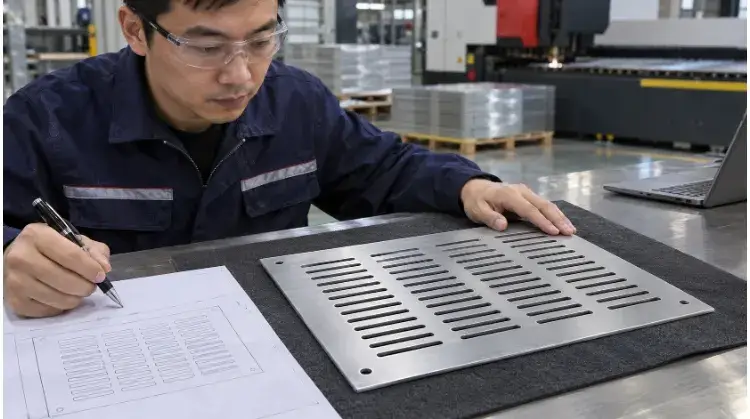
For parts with dense hole patterns or large cutouts, excessive heat can cause the entire sheet to warp. If functional requirements permit, increase the spacing between features. Leave decisions regarding cut sequencing, sheet support, and micro-joints (small tabs holding the part in the skeleton) to the supplier, as they will optimize these based on their specific machine dynamics.
Bends and Assembly
When laser-cut blanks move downstream to the press brake, the geometry near the bend lines becomes critical. Holes, slots, or cutouts placed too close to a bend line will stretch and deform during forming. To prevent this, maintain a distance of at least 1.5 times the material thickness plus the bend radius from the edge of the feature to the bend line.
Always include bend reliefs (small cutouts at the ends of a flange) to prevent the material from tearing during forming. The width and depth of the relief should generally be equal to or slightly greater than the material thickness.
Crucially, specify who is responsible for calculating the flat pattern. We strongly recommend providing the 3D model (STEP) and the final formed dimensions on a 2D PDF, rather than providing your own unfolded flat pattern (DXF). Bend deductions (K-factors) vary strictly based on the supplier’s specific press brake tooling. When the manufacturer calculates the flat pattern, they own the responsibility for ensuring the final formed part meets your dimensional tolerances.
Define Tolerances and Acceptable Cut Quality
Specifying “highest quality” on a drawing is subjective and often leads to misaligned expectations. In manufacturing, quality is defined by clear, measurable tolerances and agreed-upon acceptance criteria for edge conditions. Over-tolerancing standard profiles will unnecessarily inflate your quote, while under-specifying critical fits leads to assembly failures.
Dimensions and Holes
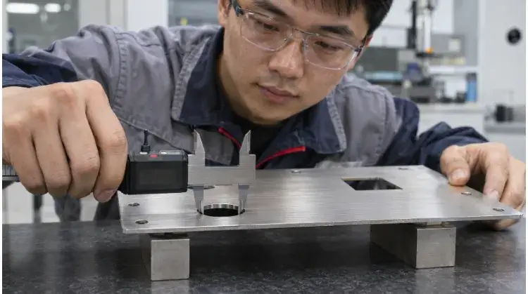
A common mistake design engineers make is confusing a laser cutting machine’s positioning accuracy (often ±0.03mm) with the finished part tolerance. The finished tolerance must account for thermal expansion, material stress relief during cutting, and kerf variations. For standard sheet metal laser cutting, a practical general tolerance is ±0.1mm to ±0.2mm, depending on thickness and material.
Do not blanket your drawing with tight tolerances. For example, specifying a ±0.05mm tolerance on a standard sheet metal outer profile means the part cannot be finished on the laser alone. It must be routed to a CNC mill for secondary edge profiling, which can increase the per-part cost by 200% to 300%. Always ask: does this edge mate with anything, or is it just sitting in the air?
When defining tolerances, explicitly state when the tolerance applies. A hole location tolerance measured on a flat blank is much easier (and cheaper) to maintain than a hole location measured across multiple formed flanges after bending.
| Feature & Function | Dimensional Requirement | Inspection Stage | Inspection Method |
| Outer Profile (General enclosure) | General tolerance (e.g., ISO 2768-m or ±0.2mm) | After flat cutting | Calipers / Vision System |
| Locating Holes (Precision alignment) | Tight tolerance (e.g., ±0.05mm) | Post-secondary machining (drilling/reaming) | Pin gauges / CMM |
| Hole-to-Hole Distance (Mating parts) | Critical tolerance across bends | After final forming | CMM / Dedicated fixture |
Cut Edges
An “as-cut” laser edge is rarely perfect. Depending on the material, thickness, and assist gas, you may see dross (resolidified metal on the bottom edge), striations (vertical drag lines on thick plates), or localized corner burning. These are inherent to the thermal cutting process, not necessarily defects.
Beware the “cheap quote” trap. When comparing quotes, a surprisingly low price often means the supplier has skipped deburring to save labor time. Receiving parts with sharp dross or oxide scale means you will pay for it later—either in delayed assembly, peeling powder coat, or injuries to your operators. Ensure “mechanical edge rounding” or “descaling” is explicitly listed on your quote, and define the required edge condition clearly.
| Observed Edge Issue | Impact on Use | Inspection / Requirement | Standard Treatment Options |
| Bottom Dross (Slag) | Prevents flat mating; cuts operators; interferes with paint. | Visual inspection; tactile check for sharp edges. | Automated edge rounding (tumbling/brushing) or manual grinding. |
| Heavy Striations (Thick steel) | Aesthetic issue; can cause stress concentrations. | Surface roughness measurement (Ra) if critical. | Accept “as-cut” if non-functional, or require secondary CNC edge milling. |
| Oxide Scale (Oxygen cut) | Paint/powder coating will flake off over time. | Tape adhesion test. | Specify nitrogen cut, or require chemical/mechanical descaling. |
Flatness and Surfaces
Laser cutting introduces intense, localized heat into the sheet. For thin materials, long narrow strips, or parts with heavily perforated regions (like speaker grilles), this heat causes internal stresses to release, resulting in warping.
When specifying flatness, define the inspection condition. A thin plate might warp 2mm when in a “free state” resting on a table, but flatten out completely under minimal pressure when bolted into its final assembly. If absolute free-state flatness is required for a highly perforated part, the factory may need to employ post-cut roller leveling operations, adding to the cost.
For cosmetic parts, clearly indicate the “show surface” on your drawings. Suppliers can use laser-grade protective films during cutting to prevent scratching, but this film must be factored into the material cost and removed prior to high-heat operations like welding.
Reduce Costs and Compare Cutting Processes
When comparing quotes from different suppliers, understanding what drives the machine time and labor will help you optimize your design for manufacturing.
Cost Breakdown
A sheet metal laser cutting quote is not just “material weight plus machine time.” The cost is distributed across several phases:
- Material: The raw sheet cost.
- Programming & Setup (NRE): Converting CAD to machine code, setting nozzle parameters, and loading the sheet. This is a fixed cost spread over your volume.
- Piercing: The time and energy required for the laser to punch through the material before it starts moving.
- Cutting Length: The actual travel distance of the laser.
- Post-Processing & Quality Assurance: Deburring, descaling, tapping, and final dimensional inspection. This is where high-quality suppliers invest, and budget suppliers cut corners.
Piercing is a major hidden cost driver. Every single hole or internal cutout requires a new pierce.
> Case Example: Consider two 500x500mm panels made of 3mm aluminum. Panel A is a solid square. Panel B has 200 small ventilation holes. Even though Panel B uses slightly less material by weight, it requires 201 pierces compared to Panel A’s 1 pierce. Panel B will take significantly longer on the machine and cost substantially more. Grouping holes into larger slots can drastically reduce pierce counts and lower the price.
Nesting and Design
Nesting is the process of arranging parts on a standard sheet to maximize material utilization. However, chasing a 95% yield shouldn’t compromise part performance.
If a part has a structural bend, the part’s orientation relative to the material’s grain direction is critical (especially in aluminum and stainless steel). Bending parallel to the grain increases the risk of cracking. A reliable manufacturing partner will sacrifice some material yield to ensure parts are nested perpendicular to the grain for safe forming.
You can lower costs by designing small parts to fit into the “drop-outs” (scrap cutouts) of larger parts. Review your designs to unify hole sizes and remove non-functional cutouts. Evaluate modifications based on the total landed part cost, rather than just isolating the machine’s cut time.
Process Alternatives
While fiber laser cutting is highly versatile, it is not always the most economical or technical choice. Knowing when to switch processes is a key sourcing skill.
If you need 50 panels with standard holes, laser cutting is king because there is zero tooling cost. However, if you need 5,000 panels with repetitive perforations, louvers, or countersinks, investing in physical tooling for a CNC Punch Press (NCT) pays for itself rapidly, often dropping the unit price significantly.
| Part Need | Alternative Process | Key Trade-offs | Conditions to Confirm |
| High-volume perforated sheets or Louvers | CNC Punching (Turret Press) | Faster per hole; can do 3D forms. Requires physical tooling (nibble marks on edges). | Tooling availability for your specific hole sizes/forms. |
| Extra-thick metal (>25mm) or Zero HAZ required | Waterjet Cutting | No heat distortion; cuts any thickness. Slower process; edge gets wet (rust risk for steel). | Abrasive cleanup requirements and dimensional tolerances. |
| Extreme precision (±0.01mm) or complex 3D profiles | CNC Machining (Milling) | Superior accuracy and edge finish. High material waste; much higher cost and cycle time. | Can specific critical features be milled after laser cutting the blank? |
Prepare Drawings and Confirm Supplier Requirements
A delayed quote or a mismanufactured batch almost always starts with an incomplete drawing package. When you hand off a design to a manufacturer, ambiguity is your biggest enemy. Clear documentation ensures you get an accurate price, a realistic lead time, and parts that actually assemble on your shop floor.
Files and Specifications
Sending a single DXF file is rarely enough, especially if the part requires bending, countersinking, or tight tolerances. The most robust RFQ (Request for Quote) package includes a combination of 3D models, 2D vector files, and a static PDF drawing.
Watch out for “dirty” DXF files. A common issue that delays quoting and ruins parts is overlapping vector lines (double lines). If your CAD software exports a DXF with double lines on a profile, the nesting software will read it twice, causing the laser to cut the exact same path twice. This destroys edge quality, widens the kerf, and doubles machine time.
Equally dangerous is layer confusion. If your bend lines are exported on the same CAD layer as your cut profile, the laser will literally slice your part into multiple pieces along the bend lines.
| File Format | Primary Purpose | Pre-Submission Checklist for Engineers |
| STEP / IGES (3D) | Viewing bent structures and overall geometry. | Ensure the model represents the final formed state, not the flat blank. |
| DXF / DWG (2D) | Direct import into the laser’s nesting software. | 1. Scale must be 1:1. 2. Delete all title blocks, dimensions, and centerlines. 3. Ensure all profiles are closed loops. 4. Remove overlapping (double) lines. 5. Put bend lines on a separate layer or delete them. |
| PDF (2D Drawing) | Specifying tolerances, threads, and finishes. | Call out exact material grades, thickness, quantities, surface finish requirements, and critical dimensions. |
Quote Comparison
Procurement managers often face a stack of quotes with wildly varying prices for the exact same CAD files. Taking the cheapest bottom-line number without reading the itemized process is a high-risk gamble.
You must verify that the quotes are an “apples-to-apples” comparison. If Supplier A quotes a nitrogen cut with automated deburring, and Supplier B quotes an oxygen cut leaving the parts “as-is,” Supplier B will look cheaper on paper. But that savings vanishes the moment your assembly team refuses to handle sharp parts, or your powder coater charges you a premium to grind off the edge oxidation.
First Article Approval
For high-volume runs, cosmetically sensitive parts, or components with critical locating features, never go straight to mass production based on a digital drawing alone. Require a First Article Inspection (FAI).
Define what constitutes an FAI pass upfront. For standard brackets, a dimensional inspection report (FAIR) and clear photos from the factory’s quality team might suffice. For complex enclosures or highly cosmetic panels, mandate that a physical sample be shipped to your facility for an assembly test.
Once the first article is approved, explicitly lock in that drawing version and the production routing. If a supplier needs to silently switch from a fiber laser to a CNC punch press later to meet capacity, they must notify you, as the edge condition and feature stress will change.
Finally, depending on your industry requirements, ensure the FAI package includes Mill Test Certificates (MTCs) to guarantee material traceability. If a supplier silently swaps to a cheaper, non-certified metal batch during mass production, your subsequent welding or forming processes will likely fail.
Stop guessing and start optimizing. Upload your CAD files (STEP + PDF) to TZR today. Our engineering team won’t just give you a price—we’ll provide a free DFM review to flag cut risks, optimize your tolerances, and help you lock in the most cost-effective production strategy.