
 English
 Spanish
 German
 Russian
 Italian
 French

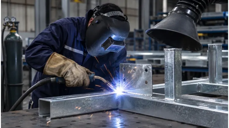
Yes, you can weld galvanized steel, but the zinc coating vaporizes before the steel melts, causing toxic fumes and weld porosity. For strong, safe joints, operators must grind away the zinc coating around the weld zone, use local exhaust ventilation, and apply post-weld corrosion repair.
Welding galvanized steel is not just a shop-floor challenge; it is a critical Design for Manufacturability (DFM) decision. Engineers and procurement teams must constantly balance structural integrity, operator safety, and unit costs. Choosing the wrong joint design or skipping pre-weld preparation leads to compromised corrosion resistance, weak joints, and significant production delays.
Before finalizing your sheet metal assembly drawings, you must define exactly what the joint needs to do. Use the quick-reference framework below to match your joint requirements with the most cost-effective manufacturing route.
| Joint Type | Initial Process to Evaluate | Verify Before Design | Key Cost Driver |
| Internal bracket lap joint | Resistance spot welding | Load requirements, two-sided electrode access | Electrode wear & maintenance downtime |
| Enclosure corner (sealed) | Continuous arc welding | Sealing requirements, post-weld distortion, repair space | Post-weld cleanup & coating repair labor |
Check the Coating and Joint Requirements
Before striking an arc, you must evaluate the base material and specific mechanical demands. Understanding these parameters ensures structural integrity and prevents costly rework.
Steel Grade, Thickness, and Coating
Before selecting a welding method, confirm the base material grade, sheet thickness, and specific zinc coating weight. For an equipment enclosure, you generally choose between two manufacturing routes: forming and welding pre-galvanized sheet metal, or welding bare steel components first and sending the entire assembly for hot-dip galvanizing.
The primary technical challenge is thermal. Zinc melts at roughly 787°F (420°C), while steel melts around 2,500°F (1,370°C). During welding, the zinc vaporizes long before the steel base melts. This rapid vaporization creates gas pockets in the weld pool, leading to porosity, excessive spatter, and toxic zinc oxide fumes.
💡 DFM Pro Tip: As a general rule, structural integrity requires grinding away the zinc coating 1 to 4 inches (25-100mm) from the weld zone before striking an arc. Failing to remove this layer often results in weak, porous welds that fail under load.
Load, Sealing, and Fit
Evaluate the functional requirements of each joint on the assembly. On a standard equipment enclosure, three distinct areas require different approaches:
- Internal brackets: Focus on load-bearing capacity and structural alignment.
- Outer corners: Evaluate for environmental sealing and visual appearance.
- Door frames: Check how thermal distortion might affect door gaps and latch alignment.
Document the cosmetic and corrosion-resistance requirements for these areas early in the project. The manufacturing process, inspection criteria, and final unit cost depend directly on these joint requirements.
Choose a Welding Process for the Joint
Selecting the right welding method dictates your production speed and final part quality. Match the process to the joint’s specific sealing and load requirements.
Spot Welding for Lap Joints
Resistance spot welding works well for lap joints, such as attaching internal brackets to an enclosure wall. The primary requirement is that the welding electrodes must be able to access both sides of the joint. You also need to confirm that the material thickness and specific zinc coating are suitable for resistance welding.
In high-volume production, the zinc coating alloys with the copper electrodes over time. Production schedules must account for frequent electrode dressing or replacement. Ignoring this accelerates tip wear, resulting in undersized weld nuggets and rejected parts.
Arc Welding for Continuous Seams
When an outer corner requires environmental sealing, a continuous arc weld is necessary to prevent moisture ingress.
For clean, indoor manufacturing of thin enclosures, pulsed MIG (GMAW) is preferred. It offers higher travel speeds and better tolerance to residual zinc. Conversely, TIG (GTAW) is rarely recommended for galvanized material. Attempting to TIG weld over zinc will contaminate the tungsten electrode in seconds, bringing production to a halt.
For outdoor structural components or thicker plates where completely removing the zinc is impractical, Flux-Cored Arc Welding (FCAW) is usually specified. Its flux system handles zinc contamination much better than solid wire, though it requires more post-weld slag cleanup.
Welding Before Hot-Dip Galvanizing
Sometimes, structural and corrosion requirements dictate welding bare steel first, followed by hot-dip galvanizing (HDG) the entire assembly. If an enclosure’s heavy-duty base requires this route, coordinate with the galvanizing facility before finalizing the design. You need to confirm maximum bath dimensions and ensure the design includes adequate venting and drainage holes.
⚠️ Design Warning: When designing parts for post-weld hot-dip galvanizing, failing to specify proper venting holes will result in trapped gases, explosive hazards in the zinc bath, and severe thermal distortion.
Evaluate the risk of thermal warping early. The heat of the galvanizing bath (around 830°F / 445°C) relieves residual welding stresses, which becomes a critical issue when large surface areas of thin sheet metal are involved in the welded assembly.
Prepare the Joint and Prevent Weld Defects
Proper joint preparation is your first defense against porosity and toxic zinc fumes. Clear the weld zone thoroughly to ensure a safe, high-strength connection.
Tool Access and Fit-Up
Consider a cross-section diagram of a lap joint. If an internal bracket’s flange is designed too close to the enclosure wall, the spot welding tongs cannot physically reach the intended weld point. For standard resistance spot welding, ensure a minimum flange width of 0.625 inches (16mm) to accommodate the electrode tips without edge expulsion.
Engineers must evaluate tool clearances and adjust the flange width or weld locations before releasing the drawing to the floor. For continuous outer seams, confirm that the final assembled geometry still allows enough physical space for a grinder to reach the joint for post-weld cleaning and coating repair.
Fume Controls Before Welding
Treat respiratory safety as a mandatory pre-weld checklist item. Before striking an arc on galvanized material, verify that local exhaust ventilation (LEV) systems are positioned to capture zinc fumes directly at the welding source.
Confirm that shop floor exposure has been formally assessed according to OSHA guidelines, and that operators are equipped with mandated respiratory protection, such as P100 filters or PAPR systems. Ignoring LEV setup not only risks operator health but halts production during safety audits.
Zinc Removal and Trial Welds
When the welding procedure specifies zinc removal, confirm that operators have the correct grinding discs and physical access to the target surfaces. The exact clearance zone and grinding parameters must follow the approved welding procedure specification (WPS).
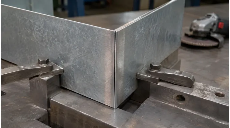
Before starting the main production run, execute trial welds on production scrap to dial in the machine settings. Use the results from these initial passes to systematically troubleshoot common galvanized welding defects.
| Trial Weld Issue | First Variables to Check |
| Porosity | Residual zinc in the weld zone, joint cleanliness, shielding gas coverage |
| Excessive spatter | Unremoved coating, unverified voltage or wire feed speed parameters |
| Suspected lack of fusion | Part fit-up gaps, gun angle/accessibility, actual travel speed |
Inspect the Weld, Fit, and Coating
Rigorous post-weld inspection verifies both structural safety and environmental sealing. Catching dimensional shifts and coating flaws early prevents downstream assembly failures.
Weld and Joint Acceptance
Separate the visual weld dimensions from the functional joint performance during inspection. Weld profiles, throat sizes, and surface conditions are checked visually against the drawing requirements.
Functional testing depends on the application. Internal brackets require performance verification (such as peel or tear tests) to confirm spot weld strength, while outer corners require designated leak testing methods to confirm sealing. Ensure the First Article Inspection (FAI) report directly maps these results to specific numbered locations on the assembly drawing.
Assembly Fit After Welding
Thermal distortion is a known variable when welding sheet metal. The primary inspection goal here is verifying that the welded enclosure still accommodates its mating components, specifically checking the door frame diagonals, panel gaps, and latch positions.
Measure critical assembly dimensions while the part is in its free state, after it has been removed from the welding fixtures and allowed to cool. Compare the result against the specific tolerances on the print (e.g., a ±0.060″ tolerance over a 3-foot diagonal). If the frame warps out of square, the door will neither close properly nor compress the weather stripping.

Coating Repair and Acceptance
Execute coating repair in a strict sequence: surface preparation, material application, and final inspection. When a project specifies ASTM A780 for repairing hot-dip galvanized coatings, accepted methods typically include zinc-rich paints, zinc-based solders, or zinc metallizing.
Welded pre-galvanized sheet metal must follow the specific repair system designated by the project requirements. The final FAI documentation must explicitly record the repaired locations, verify full visual coverage, and confirm the specified dry film thickness (DFT)—typically 2.0 to 3.0 mils—using a calibrated coating thickness gauge.
Compare Quotes on the Same Scope
Accurate cost comparison requires standardizing the manufacturing scope across all suppliers. You can only evaluate total price and lead time when every proposal guarantees the same joint function, corrosion resistance, and acceptance criteria.
Setup and Per-Part Costs
To expose hidden fees, force your suppliers to split their quotes into two distinct columns. Require them to separate one-time validation and tooling expenses from the actual per-part manufacturing cycle.
Separating these costs helps you calculate the exact break-even point for your project. A custom welding fixture adds significant upfront expense to a small prototype batch, but it becomes highly cost-effective when amortized over a large volume order.
| One-Time Setup Costs | Per-Part Manufacturing Costs |
| WPS & Trial Welds: Qualifying parameters for the specific zinc coating. | Zinc Removal: Labor for grinding clearance zones before welding. |
| Tooling & Fixtures: Custom clamping setups to control thermal distortion. | Welding & Maintenance: Cycle time and electrode dressing for spot welds. |
| Validation: First Article Inspection (FAI) and initial leak testing. | Post-Weld Processing: Cleanup, coating repair, or outsourced galvanizing. |
RFQ Checklist
Stop sending generic drawing files and hoping for accurate pricing. Attach a structured Request for Quote (RFQ) checklist to force suppliers to bid on the exact same requirements.
Instruct suppliers to explicitly state which operations are included in their unit price and which are billed separately. Require them to list any technical conditions or drawing updates they need confirmed before production kickoff.
📋 Standardized RFQ Checklist (Copy & Paste):
Please provide an itemized quote based on the exact scope below. Highlight any operations not included in your unit price.
- Drawing Revision: [Insert active revision level]
- Material & Coating: [Specify base steel grade and exact zinc coating weight]
- Volume: Initial batch of [X] units; Estimated Annual Usage (EAU) of [Y] units.
- Designated Welds: [List specific weld joints and permitted processes]
- Tolerances: Must meet critical assembly dimensions [List 2-3 key GD&T requirements].
- Performance: Joints must pass [Specify sealing, leak, or load test].
- Post-Weld Repair: Damaged coating restored per [e.g., ASTM A780].
- Deliverables: Include FAI report and coating thickness inspection logs.
- Logistics & Lead Time: Specify expected turnaround time and Incoterms (e.g., FOB, DDP).
Ready for Production?
Whether you are finalizing a prototype or scaling up to high-volume manufacturing, TZR’s engineering team can optimize your sheet metal designs for weldability, zinc coating compatibility, and cost-efficiency.
Send us your 3D CAD files and 2D prints. We will review your joint requirements, evaluate any thermal distortion risks, and return a comprehensive, itemized production quote within 24 hours.