
 English
  Spanish
  German
  Russian
  Italian
  French
Wire Electrical Discharge Machining (Wire EDM) is a precision non-contact manufacturing process that uses an electrically charged, continuously moving wire to cut through conductive metals. It relies on thermal sparks rather than mechanical force, making it ideal for cutting fully hardened alloys and achieving extreme tolerances.
Traditional CNC milling often struggles when dealing with fully hardened tool steels, sharp internal corners, or extremely deep and narrow slots. That is where Wire EDM steps in. By eliminating physical cutting pressure, this process prevents fragile parts from deforming during machining, routinely achieving tolerances down to ±0.005mm (0.0002″).
Below, we break down the shop-floor realities of Wire EDM—covering the strict design rules, actual tolerance capabilities, and what dictates your final quote.
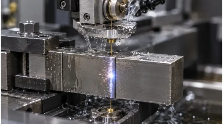
How the Wire EDM Cutting Process Works?
True precision starts with understanding the underlying physics of the machine. Let’s explore how controlled sparks, wire tension, and dielectric fluid collaborate to shape metal without physical contact.
Spark Gap and Material Removal
The process relies on a conductive wire acting as an electrode, but the wire never physically touches the workpiece. Instead, controlled electrical sparks jump across a microscopic gap (typically 0.02mm to 0.05mm) to erode small amounts of metal. The total width of the cut, known as the kerf, is formed by the wire radius combined with this spark gap.
Because there is no physical contact, the workpiece experiences zero mechanical stress. However, it is a common misconception that a “hot wire” physically slices through the material. The material removal is entirely driven by rapid, localized electrical melting and vaporization, which means the process does leave a thermal footprint on the cut surface.
Wire Tension and Dielectric Flushing
For accurate cuts, the wire must maintain a consistent tension as it travels between the upper and lower machine guides. The entire cutting zone is submerged in, or flushed with, deionized water.
This fluid is not merely a coolant; it acts as a dielectric semiconductor to control the spark discharge while actively flushing away eroded metal particles. Water quality and flushing pressure directly impact machining stability. Insufficient flushing often leads to wire breakage, surface streaks, and dimensional inaccuracies, particularly when cutting thick workpieces or deep narrow slots where debris is harder to evacuate.
Rough Cuts and Skim Passes
Wire EDM operations are divided into roughing and skimming stages. The initial rough cut removes the bulk of the material, operating at higher power to cut the primary profile.
This pass usually leaves a rough surface and slight dimensional deviations. To correct the sidewall geometry and achieve tighter tolerances, the machine performs one or more skim passes. These subsequent passes run at lower power settings, removing only microscopic amounts of material to improve surface finish (often reaching Ra 0.2µm to 0.4µm) and accuracy. In common shop terms, a “1 rough, 2 skims” process is standard for precision mold components.
Where Wire EDM Works Best—and Where It Does Not
Every manufacturing process has a specific sweet spot and strict physical limits. Knowing exactly when to deploy Wire EDM will save your team both time and budget.
Conductive and Hardened Materials
Wire EDM works well for materials including hardened tool steel, stainless steel, aluminum, copper, brass, titanium, nickel alloys, and tungsten carbide. The absolute primary requirement is electrical conductivity.
Material hardness is not a significant limitation for the cutting process itself, though thermal conductivity, melting point, and electrical resistance do influence cutting speed. A major manufacturing advantage of Wire EDM is the ability to cut parts after they have undergone heat treatment. This sequence prevents the final profile from warping during the hardening process.
However, engineers should note that cutting away material can still release pre-existing residual stresses within the metal, which may cause the final part to shift or deform after the cut is complete—especially during asymmetrical cuts on thick tool steel blocks. This is why engineering teams at TZR typically review the CAD model’s geometry and material heat-treat status before finalizing the wire path.
Through Profiles and Tapered Features
The process is highly suited for specific geometric features. Common applications include punch and die profiles, internal gears and splines, precision slots, extrusion dies, thin flexures, and complex plate contours.
Modern machines use independent U and V axes on the upper wire guide to create tapered openings. The actual achievable taper angle depends on the workpiece height, the distance between the upper and lower wire guides, and the mechanical stroke limits of the machine (often capped at around 30° to 45° depending on the equipment).
Parts Better Made Another Way
Wire EDM is not suitable for non-conductive materials like plastics or technical ceramics. It also cannot process blind holes, closed cavities, or complex 3D contoured surfaces. For bulk material removal, standard-accuracy sheet metal profiles, or high-volume low-cost simple parts, alternative methods are usually much more cost-effective.
Wire EDM is a specialized profile-cutting process, not a replacement for every CNC operation.
Design Rules for Clean, Stable Wire EDM Cuts
Designing for Wire EDM requires anticipating how the wire interacts with internal geometry and material stresses. A stable cut begins long before the machine is programmed.
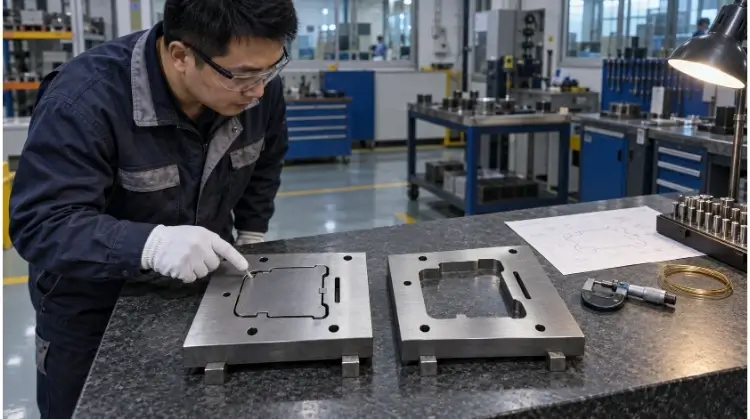
Start Holes and Wire Access
Enclosed internal profiles require pre-drilled start holes for the wire to pass through. The start hole must allow stable wire threading; undersized holes frequently lead to automated wire threading (AWT) failures. Designing a part with multiple independent internal profiles increases the number of threading cycles, which adds significant machining time (each automated re-threading cycle can add several minutes to the job, scaling up costs rapidly on multi-cavity plates).
For extremely small or deep start holes in hardened blocks, a dedicated hole-drilling EDM (often called a “hole popper”) is usually required. Engineers should strategically place start holes in the waste material (slug) and away from critical functional surfaces. We do not provide a universal start hole diameter; the optimal size must be confirmed based on the actual wire diameter and the specific machine’s threading capabilities.
Corner Radii and Kerf Allowance
The fundamental physical limit of the process is dictated by the wire. The theoretical relationship is:
Minimum inside radius ≈ wire radius + spark gap
However, the actual achievable inside radius is influenced by several operational factors, including wire diameter, spark gap, workpiece height, wire vibration, corner-control settings, and the selected skim-pass strategy.
We strongly advise engineers to leave a reasonable margin in the CAD model rather than designing to the theoretical physical limit (e.g., specifying a 0.15mm radius when using a 0.25mm wire). Please note that your engineering drawings should always specify the final part dimensions. The CAM system automatically handles the wire radius and spark gap compensation. Finally, Wire EDM cannot produce a true zero-radius internal corner.
Cutting Sequence and Part Stability
The cutting sequence directly impacts slug control and part stability. When an internal profile is completed, the heavy waste slug can drop and collide with the lower wire guide or snap the wire. This is managed using micro-joints (tabs), support plates, or destructive sectioned cutting.
Furthermore, small parts may shift during the final cut-off, and thin-walled sections often warp as pre-existing residual stresses are released. A typical, reliable manufacturing sequence involves:
- Completing heat treatment and rough machining operations.
- Establishing stable datum surfaces.
- Machining the critical internal profiles.
- Leaving necessary holding tabs for slug retention.
- Performing the final cutoff and part release.
The specific sequence must be tailored to the material, heat-treatment status, and part structure. TZR’s engineering team routinely reviews these CAD sequences to ensure the part remains dimensionally stable until the final skim pass is finished.
Brass Wire Vs. Molybdenum Wire in Production
Procurement teams often notice significant price variations across Wire EDM quotes. The underlying machine technology and wire consumption model usually explain this cost difference.
One-Way Brass Wire Systems
These systems use brass or zinc-coated brass wire that passes through the cutting zone a single time before being discarded. Because fresh, unworn wire is constantly introduced to the workpiece, these machines are highly suited for stable, multiple skim passes. They generally yield superior surface finishes and tighter dimensional control.
Consequently, both the consumable costs and the machine hourly rates are typically higher. However, specifying a one-way brass system does not automatically guarantee a fixed tolerance grade; operator setup and machine calibration remain critical.
Reciprocating Molybdenum Wire Systems
Reciprocating systems utilize a molybdenum wire that moves back and forth through the cutting zone, allowing the same spool of wire to be reused multiple times. This drastically lowers consumable costs, making it a common choice for general mold bases and standard industrial parts.
The surface finish and dimensional accuracy heavily depend on the machine’s maintenance tier. Do not confuse regional industry terms—”fast-wire” reciprocating systems do not necessarily machine faster than brass systems; the naming refers to the wire spool speed, not the actual material removal rate.
Accuracy, Finish, and Cost Differences
| Comparison Metric | One-Way Brass Wire | Reciprocating Moly Wire |
| Wire Movement | Single-direction | Back-and-forth |
| Wire Usage | Single-pass (discarded) | Reused multiple times |
| Skim Pass Stability | Usually higher | Dependent on machine tier |
| Surface Finish | Generally smoother | Generally rougher |
| Machining Cost | Usually higher | Usually lower |
| Typical Applications | High-precision molds, critical parts | General tooling, standard industrial components |
💡 TZR Engineering Tip:
Got a quote that seems too good to be true? Ask your supplier if they are using a one-way brass system or a reciprocating molybdenum system. The difference will show up directly in your part’s surface finish and final tolerances. Because TZR manages a comprehensive manufacturing network, we evaluate your drawing and route the job to the specific wire system that balances your exact tolerance requirements with your budget.
How to Control Wire EDM Tolerance and Finish?
Achieving tight tolerances requires managing physical variables that attempt to push the wire off its programmed path. Consistency depends on controlling both the machine and the environment.
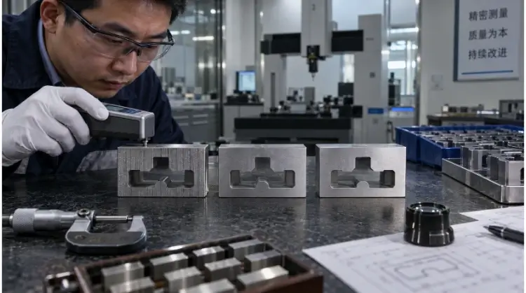
Thickness, Wire Lag, and Taper
When cutting thick workpieces or navigating sharp corners at high speeds, the middle of the wire struggles to keep up with the upper and lower guides. This phenomenon, known as wire lag or the “belly effect,” can result in corner errors, barrel-shaped sidewalls, concave profiles, top-to-bottom size variations, and unintended tapers.
The taller the workpiece, the more difficult it is for the wire to follow the exact path of the guides, often requiring significantly reduced cutting speeds to maintain vertical straightness.
Flushing, Temperature, and Machine Condition
Beyond wire lag, actual finished dimensions are influenced by dielectric temperature, workshop temperature, water resistivity, flushing nozzle position, flushing pressure, wire tension, and fixture stability.
Engineers must clearly distinguish between machine resolution, positioning accuracy, repeatability, and actual finished-part tolerance. A machine controller capable of 0.001mm display increments does not guarantee a ±0.001mm finished part if the dielectric fluid temperature is fluctuating or the flushing pressure is inadequate to clear debris.
Recast Layer and Surface Integrity
Because Wire EDM is fundamentally a thermal erosion process, it alters the surface integrity of the machined edge. Common metallurgical changes include the formation of a recast layer (often called the white layer), microcracks, local thermal stress, and surface chemistry changes. These factors are highly critical for parts subjected to cyclic loading, precision stamping dies, and components with strict surface requirements.
| Machining Strategy | Dimensional Accuracy | Surface Finish | Recast Layer Condition | Cycle Time |
| Rough cut only | Fair | Visible EDM spark marks | Relatively prominent | Shortest |
| Rough + one skim | Good | Noticeably improved | Reduced | Medium |
| Multiple skim cuts | Highest | Smoothest | Further minimized | Longest |
While multiple skim passes minimize the recast layer, they rarely eliminate it entirely on a microscopic level. Available post-processing methods to remove the remaining layer include precision grinding, lapping, mechanical polishing, controlled chemical treatment, or electropolishing where suitable. There is no single universal solution; the correct post-processing method depends entirely on the specific alloy and the required fatigue strength of the final part.
Wire EDM Vs. Milling, Laser, and Waterjet
Selecting the right cutting method dictates both part quality and final cost. Let’s compare Wire EDM against alternative processes to clarify its exact place on the shop floor.
CNC Milling
While Wire EDM and CNC milling are both precision CNC processes, they excel in fundamentally different areas.
Wire EDM works well for:
- Fully hardened conductive materials (e.g., tool steels, tungsten carbide).
- Precision through-profiles and steep tapers.
- Small internal corners (where end mills are limited by their radius).
- Deep, narrow slots.
- Fragile or thin-walled parts that would deform under physical cutting forces.
CNC Milling works well for:
- Bulk material removal at high speeds.
- Blind holes, steps, and flat-bottomed pockets.
- Complex 3D cavities and organic contoured surfaces.
- Geometries where the cutting tool has easy top-down or multi-axis access.
For many complex, high-precision components, relying on a single method is inefficient. The most practical manufacturing strategy is often a hybrid approach:
CNC milling removes the bulk material in the softer state, while Wire EDM finishes the critical profiles after the part has been hardened.
Laser and Waterjet Cutting
For flat plate and sheet materials, engineers must choose between Wire EDM, laser, and waterjet cutting based on thickness, edge quality, and budget.
| Machining Process | Primary Advantages | Main Limitations |
| Wire EDM | Highest precision (maintains ±0.005mm even on 100mm thick blocks); smallest internal radii; cuts hardened metals effortlessly. | Slowest cutting speed; strictly limited to conductive materials. |
| Laser Cutting | Extremely fast for thin profiles (optimal for sheet metal < 6mm); highly cost-effective for volume production. | Thickness limits; extreme small corners can melt due to heat concentration. |
| Waterjet Cutting | Broad material range (cuts non-metals); zero heat-affected zone (HAZ). | Edge taper is more pronounced; overall tolerances typically lag behind Wire EDM (often ±0.1mm to ±0.2mm). |
(Note: Laser and waterjet capabilities vary heavily by machine wattage and pump pressure; actual deformation or taper must be evaluated based on the specific material thickness and equipment used.)
Sinker and Hole-Drilling EDM
EDM technology is divided into three distinct machine types, each serving a specific geometric function. The selection logic is straightforward:
- Wire EDM: Used exclusively for 2D and tapered through-profiles.
- Sinker EDM (Die Sinking): Used for blind cavities, hex holes, and 3D mold impressions.
- Hole-Drilling EDM (Hole Popper): Used for creating start holes and extremely small, deep holes.
FAQs
Can Wire EDM cut blind holes?
No. Wire EDM cannot cut blind holes. The wire must pass completely through the workpiece from top to bottom. If your design features blind holes, pockets, or flat-bottomed cavities, those features must be machined using CNC milling or Sinker EDM.
Can Wire EDM cut aluminum and carbide?
Yes. Wire EDM can cut any material that conducts electricity, including aluminum and tungsten carbide. Aluminum cuts relatively quickly. Tungsten carbide cuts slower but is a prime candidate for this process because it is exceptionally difficult and expensive to machine with traditional cutting tools.
What is the minimum inside corner radius?
The absolute minimum inside corner radius is the wire radius plus the spark gap. For a standard 0.25mm wire, expect a minimum achievable radius of approximately 0.15mm to 0.17mm. Specifying a slightly larger radius (e.g., 0.20mm) in your CAD model ensures a much more stable cut.
Does Wire EDM affect fatigue strength?
Yes. Wire EDM lowers fatigue strength by creating a microscopic recast layer (white layer). Because it is a thermal process, it induces local thermal stress and potential microcracks. For parts subjected to high cyclic loading, such as aerospace components, secondary polishing or precision grinding is usually required to restore surface integrity.
Conclusion
Wire EDM is a highly specialized, indispensable tool for machining precision through-profiles, tight internal corners, and hardened alloys. However, successfully utilizing this technology requires a clear understanding of kerf allowances, starting hole placements, and the metallurgical impact of the recast layer. Designing a part that works flawlessly in CAD does not automatically guarantee it will remain stable on the machine table once residual stresses are released.
Ready to move from design to production?
Send your CAD files and drawing specifications to the TZR engineering team. Within 12 hours, we will review your geometric tolerances, evaluate your heat-treat sequencing, and provide a transparent DFM feedback report alongside an itemized manufacturing quote.