
 English
  Spanish
  German
  Russian
  Italian
  French
Spray coating for metal parts applies liquid paint or powder to enhance corrosion resistance and aesthetics. However, engineers must account for coating thickness—typically adding 20 to 100μm per surface—requiring strict DFM planning for masking, threads, and mating surfaces to prevent assembly interference.
Industrial spray coating does more than make a metal part look good—it is a critical manufacturing process that dictates how long a component survives in its operating environment. But for design engineers and buyers, the biggest challenge is not just selecting the right color. The real risk lies in the factory: preventing the paint from ruining tight tolerances, blocking internal threads, or interfering with electrical grounding points.
To avoid assembly failures and costly rework, the finishing process has to be factored in early. Here is exactly what you need to know about choosing a spray method, preparing the metal, adjusting your CAD tolerances for paint buildup, and keeping your masking costs down.
How to Choose a Spray Coating Method?
Selecting the right application method depends on the part’s geometry, production volume, and the required finish thickness. It is important to distinguish the application method (how it is sprayed) from the actual coating system (what is sprayed).
Air, HVLP and airless spray
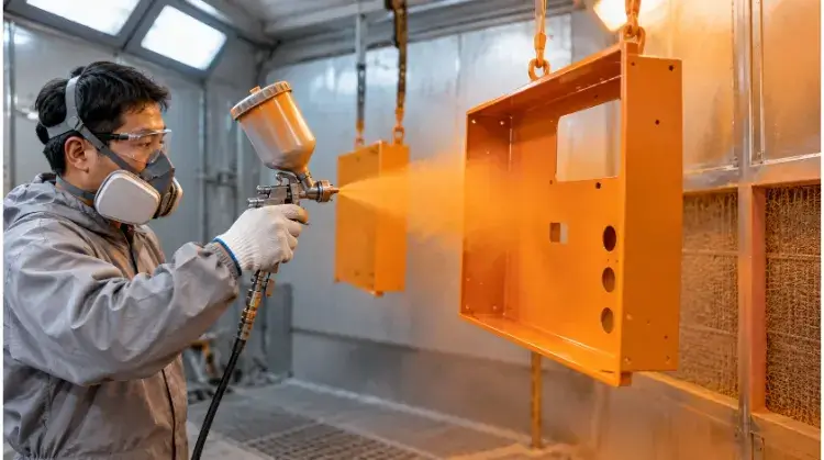
Conventional air spray uses compressed air to atomize liquid paint. It provides excellent control for complex CNC machined enclosures but generates significant overspray. High Volume Low Pressure (HVLP) systems improve transfer efficiency by using lower pressure, reducing material waste while maintaining strict control over the finish.
Airless spray relies on high fluid pressure rather than air to atomize the coating. This method applies a high volume of paint quickly and is usually used for large, flat sheet metal panels. However, it offers less control over fine details and is generally not recommended for small, intricate components.
Electrostatic spray
Electrostatic systems apply a negative electrical charge to the atomized paint particles, which are then attracted to the grounded metal part. This creates a “wrap-around” effect that significantly improves transfer efficiency on tubular frames, wire racks, or heavily vented sheet metal panels.
While efficient, electrostatic spraying has distinct physical limits. The “Faraday cage effect” causes charged particles to be drawn to the outer edges of the part, making it difficult to drive paint into deep recesses, internal corners, or blind holes. Standard air spray is often required to touch up these specific areas.
DFM Tip: To minimize the Faraday cage effect and ensure even coverage, avoid deep, narrow channels in your design and use generous internal radii (R3 or larger) wherever possible.
Liquid paint vs. powder coating
The choice between liquid paint and powder coating usually comes down to tolerance control and masking complexity. Liquid paint allows for much thinner films (typically 20-50μm) and highly precise masking, making it suitable for tight-tolerance CNC parts.
Powder coating is applied electrostatically as a dry powder and baked into a solid film. It provides a thicker (often 60-100μm+), highly durable finish that works well for heavy-duty brackets or external housings.
Tolerance Check: If your part has a general tolerance of +/- 0.05mm, powder coating will likely cause interference during assembly, making liquid paint the safer choice. Additionally, complex masking for powder coating is much more labor-intensive, which drives up piece-part costs.
| Method | Typical Use | Coverage & Appearance Control | Main Limitations |
| Conventional / HVLP | CNC enclosures, parts with intricate masking | High control over thin films | Lower transfer efficiency; higher overspray |
| Airless Spray | Large sheet metal panels, structural frames | Fast build-up; smooth finish on flat surfaces | Poor edge control; not suitable for fine details |
| Electrostatic Spray | Vented panels, tubular structures | High transfer efficiency; uniform wrap-around effect | Faraday cage effect limits coverage in deep recesses |
| Powder Coating | Heavy-duty housings, industrial brackets | Highly durable; consistent thick build | Thicker film affects tight tolerances; complex masking is difficult |
Why Surface Preparation Affects Coating Adhesion?
Coating failures rarely originate from the paint itself; they are most often traced back to the condition of the substrate before the coating was applied.
Oil, dust and fabrication residue
The manufacturing process leaves behind contaminants. CNC machining utilizes synthetic coolants, sheet metal stamping relies on forming oils, and welding generates slag and soot. If these residues are not completely removed through chemical washing or mechanical abrasion, the paint will sit on top of the contaminant rather than bonding to the metal.
Laser-cut edges require special attention. Laser cutting leaves a hard, localized oxide scale on the edge of the metal. If this scale is not mechanically sanded or removed before priming, it is notoriously prone to flaking off, taking the coating system with it.
Preparation for steel and aluminum
There is no universal preparation standard; the exact process depends on the base metal and the project specifications.
For carbon steel, surface preparation usually involves abrasive blasting to create a specific surface profile (e.g., conforming to ISO 8501-1 Sa 2.5 or SSPC-SP 10) that gives the paint a mechanical grip. Alternatively, chemical treatments like iron phosphate can be used to prevent rapid flash rusting before the primer is applied.
Aluminum forms a natural, unstable oxide layer that liquid paint struggles to adhere to directly. Machined or formed aluminum parts typically require a chemical conversion coating—such as a chromate or a non-chromate passivation (e.g., Alodine/SurTec)—to stabilize the surface and ensure long-term primer adhesion.
Matching primer and topcoat
A reliable finish relies on a coating system, not just a single layer of paint. The primer is engineered to bond directly with the treated substrate and provide primary corrosion resistance. The topcoat is formulated to bond securely to the primer while providing UV protection, chemical resistance, and the required color and gloss.
For example, an epoxy primer paired with a polyurethane topcoat is frequently specified for steel parts in outdoor industrial environments. However, the exact pairing should always follow the paint manufacturer’s technical data sheets to ensure chemical compatibility and prevent delamination between layers.
How Coating Thickness Changes Fit and Function?
Applying paint adds physical volume to a part. While this seems obvious, failure to account for coating thickness during the CAD design phase is a leading cause of assembly interference on the factory floor.
Holes and mating surfaces
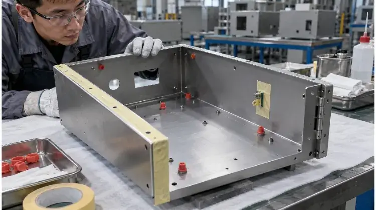
Every surface you coat grows by the thickness of the paint. If you paint an internal hole, the diameter shrinks by twice the coating thickness because the paint builds on both opposing sides.
Calculation Example: CNC Enclosure Fit
- Designed hole diameter: 10.00mm
- Liquid paint thickness specified: 0.05mm (per surface)
- Final post-coating diameter: 10.00mm – (2 x 0.05mm) = 9.90mm
If a 9.95mm locating pin needs to pass through this hole, it will jam during assembly. To prevent this, you must either specify the hole dimension as “post-coating” (forcing the machinist to drill it oversized) or explicitly mark the hole on your drawing as a “no-spray zone” requiring masking. Mating surfaces, such as the edge of a chassis door and its frame, face similar issues. If both surfaces are painted, the clearance gap between them closes by twice the paint thickness.
Threads, seals and grounding points
Internal threads smaller than M4 are notoriously difficult to mask. Remember that masking is a highly manual process. Specifying 50 individual masked holes on a single part means an operator must manually insert and remove 50 silicone plugs, which will drastically increase your piece-part price. A more cost-effective approach for small threads is to allow them to be painted and then re-tap them after curing, or to design oversized holes specifically for press-in inserts (like PEM nuts) installed after the coating process.
Surfaces intended for EMI shielding or electrical grounding must remain bare metal to ensure conductivity. O-ring grooves (glands) also require strict dimensional tolerance to seal properly against fluids or dust; paint build-up in these grooves compromises the seal and must be masked.
Masking and hanging locations
Coaters do not hold parts in their hands; they suspend them on metal hooks or wire racks to spray and bake them in ovens.
Wherever the hook touches the metal, the paint cannot reach. This leaves a small, bare metal spot known as a “rack mark.” Your engineering drawing should explicitly point out acceptable hanging locations (e.g., “OK TO HANG USING THIS HOLE”). If the entire exterior must be completely flawless, the coater will need to design custom internal fixturing to hold the part from the inside, which increases setup time and tooling costs.
DFM Tip: The clearest way to communicate masking requirements to your manufacturer is to provide a 2D PDF drawing with no-spray zones hatched in a distinct color, or to color-code the specific faces directly in your 3D STEP file.
What Causes Common Spray Coating Defects?
When a defect appears, it is rarely solved by simply blaming “bad paint.” A finish defect is the result of a system failure—usually a combination of surface preparation, ambient environment, equipment setup, and curing conditions.
Runs and orange peel
Runs (sags) and orange peel (a bumpy texture resembling citrus skin) are application and flow issues. They happen when the wet paint fails to level out properly on the metal before the solvents evaporate and the curing process begins.
Pinholes and bubbles
Pinholes look like tiny craters on the surface, while bubbles are trapped gas beneath the paint film. These are typically outgassing or contamination issues. They often originate in the factory’s air supply, from moisture trapped inside porous metal, or from applying paint when the metal temperature is too close to the dew point, which traps invisible moisture under the film.
Peeling and missed areas
Peeling (loss of adhesion) is almost always a surface preparation failure. Adhesion failure isn’t just a visual guess; it should be objectively verified using the Cross-Hatch Adhesion Test (e.g., ASTM D3359). If a part fails this tape-pull test, the root cause is typically chemical contamination or a lack of mechanical profile on the substrate. Missed areas, on the other hand, represent a physical failure to deposit paint evenly.
When a defect is identified, use the following matrix to guide your root-cause analysis rather than jumping to a single conclusion:
| Symptom | Possible Causes | Where to Check First |
| Runs / Sags | Paint mixed too thin; spray gun held too close; applying too heavy a coat. | Check the solvent thinning ratio and observe the operator’s spray distance. |
| Orange Peel | Paint too thick; shop temperature too hot causing rapid solvent evaporation; insufficient atomization air. | Check paint viscosity and verify the spray gun air pressure settings. |
| Pinholes / Bubbles | Oil or water in compressed air lines; ambient temperature too close to dew point; bake oven ramping up too fast. | Drain air compressor traps; check shop ambient humidity and the oven’s temperature ramp-up rate. |
| Peeling / Flaking | Machining oil left on metal; laser oxide scale not sanded off; missed chemical conversion coating. | Review the chemical wash tank concentration logs and mechanical sanding procedures. |
| Missed Areas (Thin spots) | Faraday cage effect in deep corners; inadequate spray angle; poor lighting in the spray booth. | Check if the part design has deep pockets; ensure manual touch-up is performed before baking. |
How to Specify and Inspect a Coated Part?
Vague drawing notes like “paint to match” or “good commercial finish” almost always lead to disputes on the receiving dock. To guarantee you get the exact finish your application requires, your engineering drawing or purchase order must define the acceptable quality in measurable terms.
Finish and masking notes
Your documentation should provide a complete baseline for the coater. At a minimum, specify the base metal alloy, the operating environment (e.g., indoor electronics vs. marine exposure), and the exact color standard (such as a specific RAL or Pantone number). You must also define the gloss level, as a matte black and a high-gloss black perform differently in hiding surface scratches. Clearly demarcate all “no-spray zones” and acceptable hanging locations directly on the drawing.
Thickness and adhesion checks
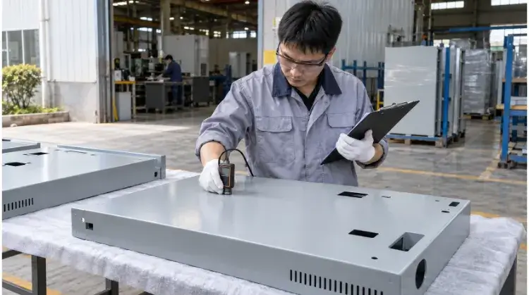
Specify the required Dry Film Thickness (DFT) range in micrometers or mils. Because paint tends to pull away from sharp edges and pool in inner radii, explicitly state where the DFT should be measured using an eddy-current gauge or magnetic thickness tester (like an Elcometer)—ideally on a flat, easily accessible surface.
If adhesion is critical, do not simply write “must not peel.” Specify the exact testing method and acceptance value, such as “Cross-Hatch Adhesion Test per ASTM D3359, minimum acceptance class 4B.” Keep in mind that your surface preparation callouts, the specified coating system, and these inspection requirements must technically align. You cannot mandate marine-grade adhesion on a steel part without also allowing the manufacturer to quote proper abrasive blasting and an epoxy primer.
Appearance and assembly acceptance
Visual inspections are subjective unless bound by rules. Define the acceptable viewing conditions, such as: “Surfaces must be free of runs, sags, and visible pinholes when viewed from a distance of 1 meter under standard daylight lighting.” Finally, note any post-coating functional checks, such as verifying that a specific mating panel fits seamlessly or that a grounding lug maintains electrical continuity.
DFM Tip: Save costs by designating surfaces on your drawing as Class A (highly visible exterior), Class B (interior but visible), or Class C (never seen). Do not pay for a flawless Class A finish on the inside of a closed chassis.
Why Spray Coating Quotes Can Vary?
Buyers are often surprised when two parts of similar overall size receive drastically different coating quotes. In industrial spray coating, the volume of the part rarely dictates the price; the true cost drivers are material transfer efficiency, manual labor, and line changeovers.
Overspray and part geometry
The shape of your part directly affects how much paint actually reaches the metal versus how much is lost to the air exhaust. A solid 1-meter by 1-meter flat panel absorbs paint efficiently. However, a 1-meter by 1-meter perforated ventilation cover might consume twice the amount of liquid paint, because the majority of the atomized material passes straight through the holes as overspray. The coater must account for this wasted material in the piece-part price.
Masking and handling time
Depending on the design, manual labor can easily cost more than the paint itself. Consider a CNC-machined chassis with 20 blind threaded holes that must remain uncoated. An operator must manually install 20 silicone plugs before painting, carefully monitor the part during baking to ensure the plugs do not degrade, and manually extract all 20 plugs after curing. This handling time is a massive cost multiplier compared to coating a solid housing that requires zero masking.
Batch size and color changes
Switching a spray line from standard black to a custom blue requires purging the fluid lines, thoroughly cleaning the spray guns, and verifying the new color profile. This setup process takes the same amount of time whether you are painting 10 parts or 1,000 parts. In small batch runs, this changeover cost is distributed across fewer pieces, leading to a much higher unit price. Standardizing your colors or consolidating your orders into larger batches is the most effective way to drive down your finish costs.
Send us your 3D STEP files, intended use, and finish requirements. Before providing a quote, our engineers will perform a free DFM review to identify masking risks, optimize hanging locations, and help you lock in a reliable, cost-effective coating strategy.