
 English
  Spanish
  German
  Russian
  Italian
  French
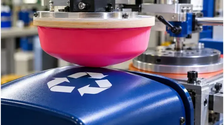
Pad printing is an indirect offset gravure process that uses a flexible silicone pad to transfer a 2D ink image from an etched plate onto a 3D object. It is ideal for printing on curved, textured, or recessed surfaces where flat screen printing cannot reach.
This guide provides the technical parameters to help you evaluate if your part is suitable, how to optimize your CAD and artwork design, and what specific metrics to check for quality approval.
How Pad Printing Works on Finished Parts?
Understanding the mechanical and physical limits of the process helps identify which design elements will transfer clearly and which factors may cause defects during production.
Plates and Pads
The process relies on two primary components: the printing plate (cliché) that holds the negative etched image, and the silicone pad that acts as the transfer medium. Because silicone is highly elastic, it compresses and deforms to match uneven, convex, or concave surfaces.
Tooling selection depends strictly on production volume and part geometry. Photopolymer plates are typically used for prototyping (lasting up to 10,000 cycles), while etched steel plates handle mass production (lasting over 1,000,000 cycles). Pad hardness (durometer) is also specified per project: harder pads yield crisper lines on robust parts, while softer pads prevent damage to fragile components.
Ink Transfer
The transfer cycle begins when the ink cup floods the etched plate and scrapes off the excess, leaving ink only in the etched cavities. Exposure to air causes the solvent in the ink to begin evaporating, making the top layer tacky.
When the pad compresses onto the plate, the tacky ink adheres to the silicone. The pad then moves and presses onto the part, releasing the ink. Note that this immediate transfer relies entirely on physical solvent evaporation, while full chemical cross-linking (curing) requires additional resting time or heat after printing.
Process Limits
While the silicone pad is flexible, it has geometric boundaries. The pad cannot reach into deep, narrow recesses or print immediately adjacent to tall vertical walls due to machine tooling clearance and pad compression angles.
Additionally, the transferred ink layer is extremely thin—typically 4 to 10 microns. This thin deposit is excellent for fine lines but makes achieving high opacity difficult on large solid areas. To overcome this on dark substrates, manufacturers often program a “double-hit” (stamping the exact same coordinate twice) to build ink thickness, though this increases cycle time.
Pad Printing Cycle Mechanics
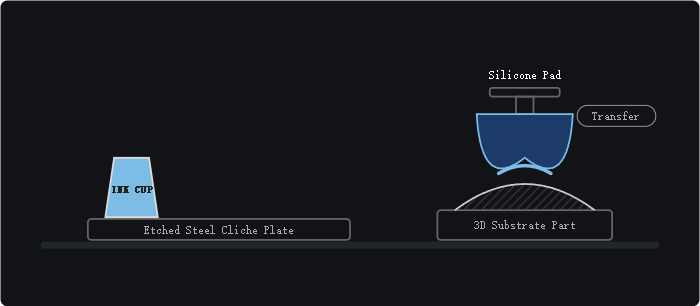
The mechanical transfer of ink happens in four distinct stages, driven primarily by the controlled evaporation of solvents:
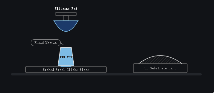
Step 1: Inking (Flood Stroke)
The sealed ink cup slides forward across the etched steel or polymer plate (cliché), flooding the recessed artwork cavity with ink.
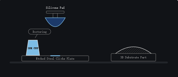
Step 2: Doctoring & Evaporation
The ink cup retracts to its home position. The hard edge of the cup acts as a doctor blade, scraping all excess ink from the flat surface of the plate, leaving ink only inside the etching. As this ink is exposed to the air, its solvents begin to evaporate, turning the top layer tacky.
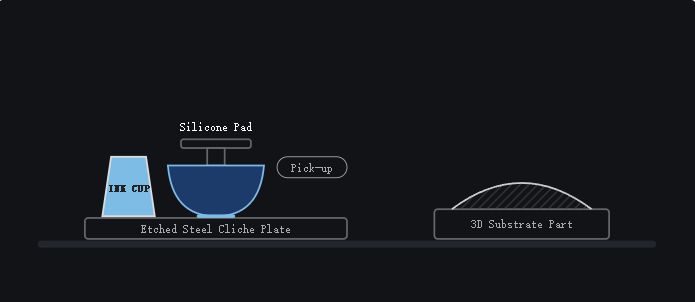
Step 3: Pick-up (Pad Compression)
The silicone pad descends and compresses onto the etched area. As the pad’s curved surface rolls outward, it pushes trapped air away and perfectly adheres to the tacky ink. When the pad lifts, it pulls the ink film out of the cavity.
Step 4: Transfer to Substrate
The pad shifts over the 3D part and compresses again, deforming to match the substrate’s exact contours. By this point, further solvent evaporation has made the ink stickier to the substrate than to the silicone pad. The pad lifts away, leaving a precise 4 to 10-micron ink deposit on the part.
When to Choose Pad Printing Over Other Methods?
Selecting the right marking process depends on the part geometry, production volume, surface material, and long-term durability requirements.
Typical Parts
Pad printing is specified for parts where a flat screen cannot make clean contact. Typical applications include scale indicators on rotary knobs, functional symbols on concave pushbuttons, and manufacturer logos on textured electronic enclosures.
In these cases, the deforming pad wraps around the local geometry. This maintains image clarity across contours without requiring complex rotary fixtures to turn the part during printing.
Coverage and Colors
The process handles fine text and precise Pantone color matching reliably. However, multi-color graphics require a separate plate, ink cup, and pad for each individual color.
The machine must register these sequentially, operating within a typical mechanical tolerance of ±0.1 mm between colors. Because of this mechanical alignment limit and the solid-color nature of the ink, complex photographic gradients or four-color process (CMYK) images are generally outside the practical scope of pad printing.
Process Comparison
- Pad Printing vs. Screen Printing: Screen printing pushes ink through a mesh, yielding a much thicker ink layer. It is the preferred method for large, flat surfaces and high-opacity requirements. Pad printing takes over when the surface has complex 3D curves, textures, or is too small for a screen to properly register.
- Pad Printing vs. UV Digital Printing: UV printing requires zero tooling, making it highly cost-effective for low volumes (under 200 units) or variable data like serial numbers. However, pad printing’s unit cost drops significantly at higher volumes, quickly amortizing the initial NRE setup fees. Furthermore, pad printing uses 2K solvent-based inks that chemically bond better to difficult engineering plastics (like POM, PE, or glass-filled nylon).
- Pad Printing vs. Laser Engraving: Laser marking physically alters the material surface, providing a permanent, consumable-free mark. Pad printing is required when strict corporate Pantone color matching is necessary, or when the physical ablation of a laser would damage a protective coating or induce rust on specific metal alloys.
Manufacturing Process Selection Guide
| Process | Ideal Part Profiles | Primary Limitations | Volume Economics |
| Pad Printing | Complex 3D shapes, textured plastics, precise Pantone colors | Very thin ink deposit; struggles with large solid blocks | High initial tooling cost, low unit cost at volume |
| Screen Printing | Flat surfaces, simple cylinders, high-opacity requirements | Cannot adapt to irregular, recessed, or complex 3D geometries | Moderate tooling cost, highly efficient for large flat areas |
| UV Digital Printing | Flat/slightly curved surfaces, full-color gradients, variable data | Slower cycle time at high volume; adhesion limits on slick plastics | Zero tooling cost, flat unit cost across all volumes |
| Laser Marking | Bare metals, specific contrasting plastics, permanent codes | Monochromatic output only; physically alters the surface structure | Zero tooling cost, fast cycle times |
How to Match Pad Printing Ink to Your Surface?
Ink adhesion depends entirely on the chemical compatibility between the specific ink system and the substrate. Selecting the wrong ink or ignoring surface conditions will result in immediate failure during quality testing.
Metals and Coatings
Ink adheres differently to bare aluminum than it does to anodized, powder-coated, painted, or electroplated surfaces. Two-component (2K) inks with specific hardeners are generally required to bond with metal and glass substrates.
Always provide your manufacturing partner with sample parts that feature the exact final surface finish. Underlying passivations or microscopic porosity changes from plating will directly alter how the ink chemically cross-links to the part.
Plastics and Pretreatment
Standard engineering plastics like ABS and polycarbonate usually accept 1-component (1K) solvent inks readily. However, low surface energy (LSE) plastics, such as Polypropylene (PP) and Polyethylene (PE), require specific pretreatment.
It is crucial to understand that cleaning a surface is not the same as activating it. Wiping away silicone mold release agents is a necessary cleaning step, but it does not change the material’s surface tension. For reliable ink adhesion, the substrate’s surface energy must generally be above 38 to 42 dynes/cm. Flame treatment or corona discharge is often required to temporarily break the molecular chains on LSE plastics, allowing the ink to wet and adhere properly.
Mixing and Curing
Pad printing ink requires a precise mixture of base color, thinner, and hardener (if using a 2K system). The thinner adjusts the evaporation rate to match the ambient temperature and machine speed.
The hardener acts as a catalyst for chemical bonding. Once mixed, 2K inks have a limited “pot life” (typically 4 to 8 hours) before they harden in the cup. Final durability—such as resistance to alcohol, solvents, or scratching—is only achieved after strict adherence to the temperature and time curing guidelines specified in the ink’s Technical Data Sheet (TDS).
Substrate and Surface Information Checklist
| Required Detail | Why It Matters for Pad Printing |
| Base Material | Dictates the choice between 1K, 2K, or specialized silicone inks. |
| Final Coating/Finish | Clear coats, anodizing, or plating change the surface energy and chemical reactivity. |
| Mold Release Agents | Residual chemicals from injection molding prevent ink adhesion and require specific cleaners. |
| End-Use Environment | Determines if the ink needs specific UV resistance, chemical resistance, or medical biocompatibility. |
How to Design Parts and Artwork for Pad Printing?
Optimizing your part geometry and 2D artwork prior to tooling reduces image distortion, prevents missing details, and lowers setup costs.
Text and Lines
To prevent ink from bridging or breaking, keep positive line widths above 0.05 mm and negative spaces (knockouts) above 0.1 mm. For text legibility, specify sans-serif fonts at a minimum of 4pt size.
The substrate’s color and texture also affect clarity. Heavily textured or matte surfaces (such as MT mold textures) will diffuse the edges of the ink deposit. If printing on a heavily textured plastic surface, lines and text should be scaled up to remain readable.
Curves and Access
The silicone pad compresses outward from its center point. Printing over sharp edges, inside deep recesses, or immediately next to tall vertical bosses restricts this compression, causing incomplete ink transfer.
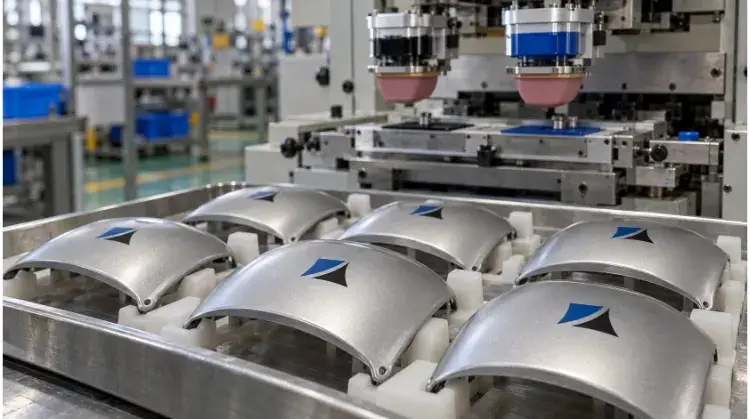
When printing onto convex cylinders or spheres, the outer edges of the 2D artwork will inherently stretch. Designers often need to pre-distort the 2D vector artwork in CAD—shrinking the edges to compensate for the pad’s stretch. Physical trial prints are always required to verify the final geometry on extreme curves.
Fixtures and Registration
Consistent printing requires a rigid fixture. The part design should include flat datums or locating pins so the part does not shift or rock when the pad strikes it.
Thin-walled plastic sections may deflect under pad pressure. To prevent this, we typically use custom CNC-machined aluminum nests or 3D-printed conformal resin fixtures to provide exact internal support. For multi-color prints, mechanical tolerances dictate a registration variance of roughly ±0.1 mm. Do not design colors that perfectly butt up against each other; incorporate a 0.2 mm to 0.3 mm safety gap, or use a “trap” (where a darker outline slightly overlaps a lighter fill color) to hide alignment shifts.
How to Fix Common Pad Printing Defects?
When printing issues occur, systematically isolating variables is critical to maintaining high yield rates and preventing production delays. Changing the thinner ratio, pad pressure, and plate simultaneously makes it impossible to identify the root cause, leading to high scrap costs.
Missing Ink
Pinholes, voids, or partial transfers usually indicate trapped air or surface contamination. First, inspect the part for residual mold release agents or machining oils.
If the surface is clean, check the pad’s shape. A pad with a steeper profile helps roll the air outward during compression, preventing trapped air bubbles. Alternatively, the ink may be drying too quickly in the etched plate before the pad can pick it up, requiring a slower-evaporating thinner.
Smearing and Distortion
Blurry edges, ghosting, or “stringing” (where ink pulls into fine webs during pad lift) often mean the ink is too tacky. This is typically solved by adjusting the thinner ratio or lowering the pad’s lifting speed.
If the image looks heavily stretched or distorted, the mechanical setup is likely at fault. Verify that the pad is not over-compressing onto the part, and check the fixture to ensure the part is not shifting during the pad’s downstroke.
Color and Adhesion
Mottled or uneven solid colors are often a physical limitation of the thin ink deposit rather than a defect in the ink itself. A double-hit cycle may be required for acceptable opacity.
If the ink transfers cleanly but flakes off during a cross-hatch or tape test, the issue is chemical. Differentiate between a transfer failure on the machine and a post-cure adhesion failure. Adhesion failures indicate that the ink system is incompatible with the substrate, the substrate requires surface activation, or the parts were not cured at the correct temperature for the required duration.
Troubleshooting Protocol for Pad Printing
| Symptom | Possible Cause | Priority Check | Verification Method |
| Pinholes / Voids | Trapped air or surface contamination | Pad profile angle; surface cleanliness | Switch to a steeper pad; wipe part with IPA. |
| Stringing / Blurry Edges | Ink viscosity / timing | Thinner ratio; pad lift speed | Add retarder (slow thinner); reduce machine speed. |
| Image Distortion | Mechanical movement / over-compression | Part fixture rigidity; pad stroke depth | Reduce downstroke limit; verify part does not rock. |
| Fails Tape/Scratch Test | Chemical adhesion failure | Material dyne level; curing schedule | Run flame treatment; verify oven temperature & time. |
How to Inspect Pad Printed Parts Before Delivery?
Approving a pad printed part is not just about confirming it looks good straight off the machine. A rigorous inspection protocol ensures the print remains durable in its end-use environment and that mass production perfectly matches the approved sample.
Appearance and Position
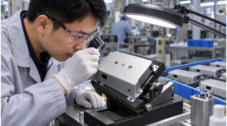
Visual inspection should always be conducted under standardized lighting (such as D65 standard daylight) at a typical viewing distance of 18 inches (45 cm). Inspectors look for unbroken text, solid color opacity, and the absence of pinholes or blurry edges.
When verifying print position and multi-color registration, measurements must be taken from a strict physical datum on the part (like a mounting hole or a machined edge). Avoid measuring from injection molding parting lines or flash, as these can shift from batch to batch. Once approved, this physical part becomes the “Golden Sample.” It is sealed in a UV-blocking dark bag and stored in a QA lab to serve as the absolute baseline for all future production batches, preventing any color-drift over the product’s lifecycle.
Adhesion and Durability
Ink transfer happens instantly, but chemical cross-linking does not. Never perform destructive testing immediately off the press. Wait for the ink’s specified curing time (typically 24 to 72 hours at room temperature, or immediately after oven baking) before testing.
Durability is verified through standardized testing based on the part’s application. The most common metric is the ASTM D3359 cross-hatch tape test for adhesion. Wear resistance is often tested using an RCA abrader, while chemical resistance is verified using solvent rub tests (e.g., wiping the print with 99% IPA or MEK to check for ink transfer). For mass production runs, these destructive tests are performed on a statistical sampling basis according to AQL (Acceptance Quality Limit) standards, such as ISO 2859-1 Level II, ensuring batch consistency without unnecessary part wastage.
First Article Approval
The First Article Inspection (FAI) report locks in the production variables. It must explicitly record the exact vector artwork version, Pantone color match, ink series, hardener ratio, and the specific substrate finish.
If there is any change in the supply chain—such as switching the injection molding resin supplier, altering the surface texture (MT number), or using a different mold release agent—the existing FAI is voided. A new sample run and adhesion test must be conducted to re-validate the process.
First Article Inspection (FAI) Checklist for Pad Printing
| Inspection Category | Test Method / Tool | Standard Acceptance Criteria |
| Visual Quality | Visual under D65 lighting at 18″ | No pinholes, missing ink, or visible stringing. Text ≥ 4pt is fully legible. |
| Color Match | Spectrophotometer / Pantone Book | ∆E (Delta E) ≤ 2.0 against the target Pantone reference. |
| Position & Registration | Digital Calipers / CMM | Center point within ±0.2 mm of datum. Multi-color registration within ±0.1 mm. |
| Adhesion | ASTM D3359 Cross-Hatch Test | Classification 4B or 5B (Less than 5% of ink removed by certified tape). |
| Chemical Resistance | Solvent Rub Test (e.g., IPA wipe) | No visible ink transfer to the wipe after 50 continuous rubs at 1kg pressure. |
Get Your Parts Pad Printed Reliably
Pad printing requires a delicate balance of mechanical precision, chemical compatibility, and environmental control.
Ready to move from design to production?
Send us your 3D CAD models, 2D vector artwork (.AI, .EPS, or .DXF), and substrate specifications. Our engineering team will provide a comprehensive DFM review and a transparent quote for your custom manufacturing and pad printing needs.