
 English
  Spanish
  German
  Russian
  Italian
  French
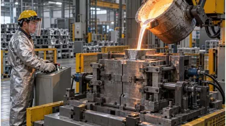
Permanent mold casting is a metalworking process that uses reusable steel or cast iron molds to produce highly dense, non-ferrous metal parts. It delivers better mechanical strength and tighter tolerances than sand casting, making it the optimal choice for medium-to-high volume aluminum and zinc components.
Before diving into DFM rules and tooling costs, you must determine if this process aligns with your production reality. Selecting this method requires a joint evaluation of your structural requirements and financial targets. Use the checklist below to quickly evaluate if your project is a match:
| Evaluation Factor | What You Need to Confirm |
| Material | Specific alloy grade and temper (e.g., A356-T6 vs. As-Cast) to determine post-machining hardness. |
| Structure | Draft angles (typically 2-3°), need for sand cores (adds cost), and wall thickness uniformity. |
| Accuracy | As-cast tolerances vs. post-machining dimensions, noting where CNC is mandatory. |
| Volume | Expected annual demand and design stability (modifying metal tools is expensive). |
| Post-Processing | Heat treatment capability, coating adhesion, and NDT (Non-Destructive Testing) requirements. |
How Permanent Mold Casting Works?
A successful casting relies on a precisely controlled production cycle. Let’s break down how each manufacturing phase directly impacts your part’s final quality and structural integrity.
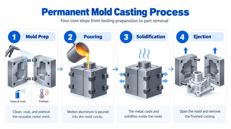
Mold Preparation
The production cycle begins with tooling preparation. The metallic mold halves—typically machined from cast iron or H13 tool steel—are preheated to an operating temperature between 150°C and 260°C (300°F–500°F) for aluminum alloys. Preheating maintains metal fluidity and prevents immediate thermal shock to the tool.
Next, a refractory coating is applied to the cavity surfaces to act as an insulating layer and prevent the molten metal from soldering to the mold. If the part requires internal cavities, sand cores (in semi-permanent molding) or removable metal pins are positioned before the mold is clamped. Quality Impact: The thickness and application technique of this refractory coating directly affect the final dimensional tolerance and surface finish consistency.
Filling and Solidification
Once the mold is closed, molten metal is introduced. In standard gravity pouring, the metal flows down the sprue by its own weight. To reduce turbulence and minimize oxide entrapment, facilities often use tilt-pour mechanics, where the mold is rotated during filling, or low-pressure casting to push the melt upward smoothly.
Solidification is the most critical phase for quality control. Foundries manage directional solidification through specific gating designs, mold venting, and localized temperature controls so the part feeds properly as it shrinks. Quality Impact: Poor directional solidification is the leading cause of internal shrinkage porosity, which is often only discovered later during costly CNC machining.
Ejection and Finishing
After the part cools sufficiently, the mold opens and ejector pins push the casting out. The as-cast part still has the gating system, runners, and risers attached, which are typically removed via band saws or trimming presses. If sand cores were used, they are vibrated or baked out of the internal cavities.
At this stage, the raw casting is ready for subsequent operations. This usually involves heat treatment to meet mechanical property requirements, followed by CNC machining to achieve final tolerances on functional surfaces. Quality Impact: If insufficient machining allowances are left during the design phase, CNC cutters will hit the hard, abrasive as-cast outer skin, leading to rapid tool wear and poor machined finishes.
When to Choose Permanent Mold Casting?
Selecting the right fabrication method means balancing upfront tooling costs against expected production volumes. Review these key comparisons to determine if this process meets your structural and financial targets.
Part Features and Demand
Permanent mold casting works well for parts that require higher mechanical strength and lower porosity than sand casting, but do not have the volume to justify high-pressure die casting (HPDC) tooling. From a cost perspective, the process typically reaches the lowest cost-per-part between 1,000 and 20,000 units annually.
Structurally, it accommodates thicker and varying cross-sections better than HPDC, though it still requires controlled wall thickness transitions to prevent shrinkage defects. Because modifying a CNC-machined steel mold is expensive, this process should only be selected when your product design is stable and frequent geometric changes are not expected.
Sand Casting Comparison
Compared to sand casting, permanent mold tooling requires a higher initial investment because the molds are cut from metal alloys rather than formed from sand patterns. However, the reusable metal mold yields parts with tighter dimensional consistency—typically ±0.015 inches for the first inch.
It also produces smoother surface finishes, generally ranging from 150 to 400 RMS. This directly reduces the amount of secondary CNC machining required, offsetting the higher tooling cost over a production run. Sand casting remains the preferred method for highly complex, undercut geometries or low-volume pilot runs.
High-Pressure Die Casting Comparison
HPDC injects metal at high speeds and pressures, making it suitable for extremely thin walls (down to 1.5mm) and high-speed production rates. However, HPDC tooling requires a significantly larger upfront investment. While HPDC dies can last 100,000+ shots, permanent molds typically experience thermal fatigue (heat checking) after 30,000 to 50,000 pours, requiring maintenance or replacement.
A critical distinction lies in material integrity. HPDC parts often contain entrapped air porosity, meaning they generally cannot be welded or subjected to high-temperature heat treatments (like T6) without blistering. Permanent mold castings solidify denser, allowing for full heat treatment, making it a standard choice for pressure-tight components like hydraulic manifolds and structural brackets.
How to Choose Alloys and Heat Treatments?
Material selection dictates both your part’s field performance and its manufacturability. Aligning your alloy grade and heat treatment with specific service conditions prevents premature failure.
Aluminum Alloy Selection
A356 and 319 dominate permanent mold casting due to their excellent fluidity and resistance to hot tearing. However, when specifying these grades, engineers must also define the required temper state—such as As-Cast (F) or T6—as this dictates the final mechanical baseline.
Leaving the temper undefined often leads to parts that are either too soft for structural loads or too brittle for impact. Always confirm material data sheets with your foundry to ensure the alloy’s fluidity matches your wall thickness requirements.
Strength and Service Conditions
Selecting the right alloy depends entirely on operational stresses rather than generic industry labels. For pressure-tight applications like hydraulic valves, A356 works well because its narrow freezing range minimizes shrinkage porosity, preventing fluid leaks under continuous load.
If the part operates in corrosive environments or high-temperature zones, alloys with higher silicon or magnesium content may be required. Always evaluate expected mechanical loads, operating temperatures, and exposure to harsh chemicals before finalizing the material choice.
Heat Treatment and Distortion
Heat treatments like the T6 cycle (solution heat treating and artificial aging) significantly increase tensile and yield strength. However, the rapid quenching involved in these processes introduces residual stresses that may cause long or flat parts to bow out of tolerance.
To manage this distortion risk, foundries often rough-machine the part before heat treatment or use specific quenching media. You must coordinate the machining sequence with the heat treatment schedule to maintain critical dimensional tolerances.
How to Design Parts for Permanent Molds?
Good design minimizes defect risks and reduces tooling complexity. Following strict design-for-manufacturability (DFM) rules directly lowers your per-part costs and improves production consistency.
Wall Thickness and Radii
Uniform wall thickness is the most critical factor in preventing shrinkage porosity and hot tears. In permanent mold casting, sections that are too thick take longer to solidify, creating isolated hot spots that draw metal away from surrounding areas as they cool.
To mitigate this, design smooth transitions between varying wall thicknesses using generous radii rather than sharp internal corners. Hollow out bulky bosses or use ribs to maintain structural strength without adding unnecessary mass.
Draft and Parting Lines
As molten metal cools, it shrinks and grips the rigid steel mold tightly. To allow for proper ejection without damaging the part, you must apply sufficient draft angles—typically 2° to 3° on vertical walls—perpendicular to the parting line.
Avoid complex undercuts whenever possible. Undercuts require moving slides or side-actions within the mold, which not only increase the initial tooling investment but significantly drive up long-term maintenance costs.
Core Support and Removal
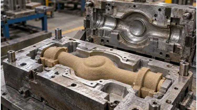
When internal channels or cavities are necessary, expendable sand cores are placed inside the permanent mold. Because sand cores are highly buoyant in molten metal, they require robust support points—known as core prints—to prevent them from shifting or floating during pouring.
Always design adequate exit openings for core removal after the casting solidifies. As a rule of thumb, ensure cleanout holes are as large as functionally possible—typically no less than 15mm in diameter—to allow for effective sand shakeout.
How to Set Tolerances and Machining Allowances?
Proper tolerance allocation prevents costly disputes between the foundry and the machine shop. Defining clear boundaries ensures functional surfaces meet specs without removing excessive material.
Casting Variation
As-cast tolerances must account for natural volumetric shrinkage, minor mold misalignment across the parting line, and potential core shifting. Additionally, high-temperature heat treatments can introduce slight warping, moving the part outside of its original cast dimensions.
Do not apply tight CNC-level tolerances to raw casting blueprints. Instead, use standard foundry tolerances for the as-cast state, and reserve strict geometrical tolerances exclusively for post-machined functional features.
Machining Allowances
A machining allowance is the extra material left on the casting specifically to be cut away later. Leaving too little allowance means the cutting tool might skip over low spots, failing to clean up the surface entirely.
Conversely, leaving excessive material forces the CNC machine to cut deeper into the softer, more porous center of the casting, which compromises the surface finish and exposes internal defects. A standard allowance of 1.5mm to 2.5mm (0.060″ to 0.100″) is usually applied.
Datums and Functional Surfaces
To ensure dimensional consistency, the casting drawing and the machining drawing must share the exact same datum reference frame. This ensures the part is fixtured identically every time it enters the CNC center.
Never place datum targets on the parting line, draft angles, or areas where gates and risers will be trimmed, as these surfaces have the highest natural variation. Clearly highlight critical functional areas so the foundry can place gates away from these defect-sensitive zones.
What Drives Permanent Mold Casting Costs?
Evaluating a quote requires looking beyond the raw piece price. Understanding the full cost lifecycle prevents unexpected expenses and ensures accurate ROI calculations.
Tooling and Breakeven
Metal tooling represents a significant upfront capital expenditure compared to sand patterns. However, this fixed cost is amortized across the production run, dropping the per-part cost significantly as volumes increase.
To calculate your true breakeven point, compare the total amortized cost of a permanent mold against a sand casting process over your expected annual demand. Generally, permanent mold becomes highly cost-effective when cumulative volumes cross the 1,000-unit threshold.
Maintenance and Design Changes
Unlike sand casting, metal molds require ongoing maintenance to prevent degradation and ensure part consistency. Refractory coatings must be periodically stripped and reapplied, and thermal fatigue will eventually necessitate weld repairs or recutting.
Additionally, modifying a CNC-machined steel tool to accommodate a design change is highly expensive. This is why designs must be strictly finalized before tooling begins, and why buyers should clarify who covers routine tool maintenance in the purchasing contract.
Finishing and Inspection
A comprehensive quote must encompass the entire manufacturing sequence, not just the poured metal. Complex sand cores, T6 heat treatments, CNC machining, and specialized surface coatings add significant labor and machine time.
When comparing foundry quotes, always verify whether secondary operations and testing are included. Most importantly, ensure the quote explicitly outlines who absorbs the financial loss if scrap parts—and their added high-value machining costs—are rejected due to internal defects discovered late in the CNC process.
How to Verify Casting Quality Before Delivery?
Consistent quality control requires aligning inspection methods with functional requirements. Establishing clear acceptance criteria early prevents costly downstream assembly failures.
Internal Defects
Internal casting defects generally fall into three categories: gas porosity, shrinkage porosity, and oxide inclusions. Shrinkage porosity is particularly dangerous if it occurs near a machined sealing face, as it will cause immediate leakage once the dense outer skin is removed.
Do not rely on verbal agreements for internal quality. Specify acceptable porosity levels on your drawings using non-destructive testing (NDT) such as X-ray radiography (RT) or Dye Penetrant Inspection (PT), mapped against standardized reference radiographs (such as ASTM E155). This ensures the foundry knows exactly where defects are strictly prohibited.
Dimensions and Surface
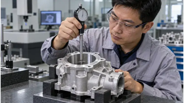
Inspecting the raw casting requires verifying critical datums and ensuring sufficient machining allowances remain. Visual inspections must also define acceptable criteria for surface irregularities, such as cold shuts, minor flow marks, or coating textures.
Be explicitly clear about the acceptable witness marks left behind after gate and riser removal. If a specific face is cosmetic, the foundry must know in advance to place gating systems elsewhere or grind the area flush.
Functional Tests and Approval
For fluid-handling components like hydraulic blocks or valve bodies, pressure or helium leak testing is a mandatory functional verification. Structural parts should require mechanical property validation using separate test bars poured from the exact same melt batch as the production parts.
Always establish a strict First Article Inspection (FAI) protocol. This ensures the foundry’s gating design, cooling rates, and dimensional controls are fully approved before authorizing a full-scale production run.
Ready to evaluate permanent mold casting for your next project?
Submit your 3D CAD models, 2D drawings with tolerances, and estimated annual volumes under NDA. Our engineering team will review your DFM within 48 hours to identify cost-saving opportunities and provide a comprehensive tooling and production quote.