
 English
 Spanish
 German
 Russian
 Italian
 French

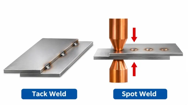
A tack weld is a temporary arc weld used to hold parts in alignment before final welding. In contrast, a spot weld (resistance spot welding) uses pressure and electrical current to form a permanent, internal fused nugget between overlapping sheets, serving as the final structural joint.
Specifying the wrong joining method on a manufacturing drawing leads to severe thermal distortion, tooling clearance issues on the shop floor, or expensive rework. To keep the specifications clear, spot welding in this article refers specifically to resistance spot welding (RSW).
It is crucial to understand that these two terms operate at different conceptual levels: a tack weld describes an assembly function (which can be done via MIG or TIG), while spot welding is a distinct manufacturing process.
The table below outlines the baseline differences in how they are applied on the shop floor.
| Comparison Area | Tack Weld | Spot Weld (RSW) |
| Primary Purpose | Temporary fixturing prior to final welding | Permanent connection for overlapping sheets |
| Typical Equipment | MIG, TIG, or Stick arc welders | Resistance spot welding machine |
| Joint Configuration | Fillet, butt, lap, or corner joints | Primarily lap joints |
| Subsequent Steps | Fused into the final weld or ground off | Usually none; serves as the final joint |
| Inspection Focus | Position accuracy, tack size, no cracks | Internal nugget size, pull/peel strength |
Understand the Difference Between Tack and Spot Welds
To specify the right joining method, it helps to look at how the connection is formed and how it behaves in an assembly. Visual appearance alone is not a reliable indicator of the weld’s structural capability.
Tack Weld Purpose
Tack welding functions as a temporary constraint. Its primary role is to maintain the correct angles, dimensional tolerances, and assembly gaps against the thermal expansion and contraction that occur during the final welding pass.
Because it is an assembly technique, operators typically use the same process intended for the final joint, such as MIG or TIG. Depending on the welding procedure, a tack weld is either completely fused and consumed by the final weld pass or ground off beforehand if it interferes with the required bead profile.
Spot Weld Formation
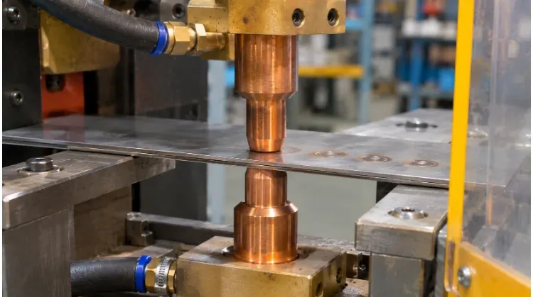
Resistance spot welding works by clamping overlapping metal sheets between copper alloy electrodes. The machine applies specific pressure and passes a high current through the materials. The electrical resistance at the interface generates concentrated heat, melting the metal to form a localized, internal fusion zone known as a nugget.
Unlike a tack weld, which adds filler metal or melts the visible edges of a joint, a proper spot weld forms entirely between the mating surfaces. The visible marks on the exterior are usually just shallow indentations. It is necessary to distinguish this process from plug welding (filling a pre-drilled hole using MIG/TIG) or the “spot timer” function on MIG machines, which are arc welding operations, not true resistance welding.
Assembly Examples
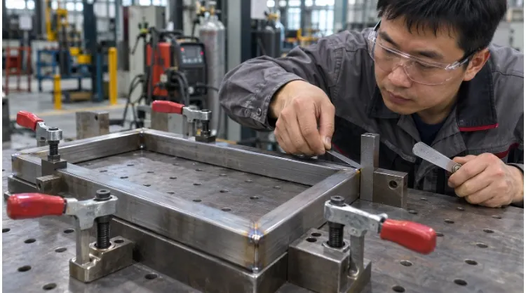
The application determines the choice. When assembling a rigid equipment frame made of square tubing, tack welds hold the cross-members square while the welder checks the diagonal measurements before completing the full structural welds. Conversely, when attaching stiffening ribs to a sheet metal enclosure, resistance spot welding provides a fast, permanent connection along the lap joint without the heat distortion that continuous arc welding would cause.
If a design changes, these methods cannot simply be swapped one-to-one. Replacing a continuous arc weld with a series of spot welds requires re-evaluating the complete joint geometry from a corner or butt joint to a lap joint with sufficient flange width.
Check Whether the Joint Suits the Process
Determining if a part is manufacturable requires evaluating the physical space available for the tooling and how the materials respond to the selected process.
Joint and Access
The physical dimensions of the joint dictate whether the equipment can reach the weld location. For spot welding, the design must include an adequate lap width to contain the molten nugget and prevent edge expulsion. A standard rule of thumb for edge distance is typically at least 2 times the material thickness plus the electrode radius. There are also strict requirements for weld pitch (distance between adjacent spot welds) to prevent the shunting effect, where electrical current bypasses the intended weld location and flows through the adjacent, already-completed welds.
Tooling clearance is equally critical. A pedestal spot welder requires sufficient throat depth to reach the center of the panel, and the electrodes must clamp from both sides simultaneously. If the bending sequence restricts electrode access, a plug weld may serve as a fallback option, though this requires updating the drawing and validating the new joint strength. For tack welding, the operator needs enough clearance to position the welding torch at the correct working angle, especially in deep channels.
Material Stack
Material specifications directly impact process feasibility. For spot welding, variables include the material grade, the thickness of each layer, and surface coatings. Galvanized steel, for example, alters the contact resistance and accelerates electrode wear, requiring more frequent electrode dressing and tighter process control.
When joining dissimilar thicknesses or stacking three or more sheets, the heat balance shifts. While reference tables provide general thickness limits, actual manufacturing limits depend on the specific machine’s kVA rating and clamping force. Rather than relying on universal maximum thickness guidelines, factories typically run weld trials on exact material coupons to confirm proper nugget formation.
Product Requirements
The intended use of the component defines the acceptance criteria. Engineers must evaluate the expected load directions; spot welds handle shear loads well but are highly susceptible to peel and tensile stresses, because the stress concentrates directly at the edge of the fused nugget. If the joint requires a continuous liquid or gas seal, intermittent spot or tack welds will not suffice without additional sealants or continuous seam welding.
Appearance requirements also restrict the choice. Spot welding will leave a slight depression and possible heat tint on the visible side. While a flat copper backing electrode can minimize marking on the cosmetic face (a “show surface”), it rarely eliminates it entirely. If a perfectly flat finish is required, the design may need hidden weld studs or carefully placed and ground tack welds prior to a full finishing operation.
Control Fit-Up and Welding Distortion
Maintaining gap, position, and dimensional accuracy during welding is a battle against thermal expansion and contraction. How you manage the joint prior to and during the welding process determines whether the final part meets tolerance or requires expensive straightening.
Tack Placement
Proper tack placement locks the assembly against weld shrinkage. The number, length, and location of tack welds must provide enough rigidity to counteract the pulling forces of the final weld pass. As a general rule, tack length should be 2 to 3 times the thickness of the thinnest material, providing enough cross-section to hold the joint without requiring excessive grinding later.
Rather than relying on a universal fixed spacing, engineers should base tack placement on the material gauge and component stiffness. A common best practice is to place tacks from the center of the seam outward, pushing any potential distortion toward the free edges.
Heat and Sequence
Concentrated heat input alters the material and causes warpage. For arc welding, techniques like skip welding or back-stepping distribute the heat load across the part, preventing localized overheating and burn-through on thin sheets.
It is also critical to understand the metallurgical impact of temporary heat. Because tack welds are small, they cool incredibly fast. On hardenable materials like high-carbon steel, this rapid quenching can form brittle martensite, leading to micro-cracks in the tack weld that compromise the joint before the final weld is even applied. In these cases, adjusting the weld sequence or applying localized preheating becomes a mandatory process step.
Fixtures and Settings
A weld should never be used to force poorly cut parts together. Proper pre-weld fit-up and clamping ensure the weld isn’t bridging excessive gaps, which introduces severe distortion.
For spot welding, maintaining dimensions relies heavily on the machine’s weld schedule. This includes regulating the squeeze time (pressure before current), weld time, and hold time. The hold time is particularly critical because the water-cooled copper electrodes act as a heat sink. Releasing pressure too soon causes “hot tearing” (cracking) within the nugget, completely compromising joint strength. Process control requires operators to establish clear inspection nodes for key dimensions, adjusting fixtures immediately if alignment begins to drift.
Compare Complete Assembly Costs
Evaluating the true manufacturing cost requires looking well beyond the actual arc time. A process that seems faster on paper can quickly become the more expensive option when setup, handling, and rework are factored into the cycle.
Setup and Volume
Spot welding generally demands a higher initial investment. It requires dedicated copper electrodes, specific fixture alignments, and destructive testing (such as peel or tear tests) to pass First Article Inspection (FAI).
While manual tack and arc welding is ideal for prototype batches or designs with frequent revisions (e.g., 1 to 50 units), the high CapEx of a spot welding cell typically becomes cost-effective when production volumes scale into the hundreds or thousands. The high initial setup costs of spot welding are easily amortized over high-volume production runs, whereas manual tacking relies on standard equipment and flexible fixturing, keeping upfront costs low.
Cycle and Automation
Cycle time calculations must include part clamping, welding, handling, and flipping. Spot welding excels in sheer speed, forming a joint in fractions of a second. However, maneuvering a large, heavy chassis to fit inside the throat of a pedestal spot welder can take longer than the welding itself.
Volume and repeatability justify automation, but automation is not universally cheaper. Robotic tack welding or automated spot welding cells drastically reduce cycle times, but they require high CapEx and ultra-precise, expensive bespoke fixturing. If the sheet metal blanks are out of tolerance, the robot will simply and consistently produce bad parts.
Finishing and Rework
The most overlooked costs occur after the welding stops. Tack welds that sit proud of the surface must often be ground flat, requiring significant manual labor, abrasives, and cleaning. Spot welding eliminates filler material and grinding, but introduces its own hidden costs: electrode maintenance (frequent tip dressing) and severe rework penalties.
If a tack weld is misplaced, an operator can gently grind it out and reposition the part. If a spot weld is misplaced, it is a permanent fusion. Separating the panels requires a specialized spot weld drill bit, resulting in destructive rework that often destroys the base metal and leads to part scrap.
Assembly Cost Comparison Summary:
| Cost Variable | Tack Weld + Final Arc Weld | Resistance Spot Weld |
| Process Prerequisite | Final weld bead meets joint load and cosmetic requirements. | Spot pattern and nugget strength verified via testing. |
| Setup Investment | Flexible fixturing, visual/dimensional trial, WPS confirmation. | Rigid fixturing, custom electrodes, destructive FAI testing. |
| Total Cycle Time | Includes clamping, sequential tacking, final weld passes, and cooling delays. | Includes clamping, extremely fast weld cycles, and part maneuvering/handling. |
| Downstream Costs | Slag removal, grinding, cosmetic finishing, and dimensional straightening. | Electrode tip dressing, routine nugget testing, and expensive destructive rework. |
(Note: Actual labor hours and financial costs must be calculated based on the specific material, production volume, equipment availability, and final acceptance criteria.)
Specify and Verify Weld Quality
A well-designed joint will still fail if the quality requirements are not explicitly communicated to the shop floor. Vague drawing callouts lead to inconsistent manufacturing, leaving operators to guess the intended acceptance criteria.
Tack Weld Acceptance
Unlike final structural welds, tack welds are frequently under-specified on drawings. Rather than leaving simple “tack here” notes, engineers should use standard AWS or ISO welding symbols to explicitly define the tack length, pitch, and post-weld finishing requirements.
A proper manufacturing specification must dictate whether the tack will be consumed (melted into the final weld pass), left as-is, or ground flush before proceeding. Inspectors evaluate tack welds for correct placement, adequate profile, and the absence of visible defects such as porosity or cracks. If a tack weld fails visual inspection or misaligns the assembly, it must be removed. The quality specification should mandate that the removal process (typically grinding) does not gouge or thin the base metal beyond allowable tolerances. Once an out-of-spec tack is removed, the dimensional fit-up must be completely re-verified before the operator applies a new tack.
Spot Weld Verification
Spot weld quality cannot be determined by surface appearance. While a visual check ensures the electrodes left acceptable indentations without severe expulsion (metal splatter) or deep surface cracks, true verification requires testing the internal nugget.
Because the actual connection is hidden, shop floors rely on destructive testing for First Article Inspection (FAI) and regular interval sampling. Common methods include the peel test or chisel test—where sample welded sheets are forcibly driven apart to measure the diameter of the pulled nugget—and metallurgical cross-sectioning.
However, buyers should balance strictness with budget—over-specifying destructive testing on non-critical parts will unnecessarily inflate the unit price. Your RFQ (Request for Quote) must define the sampling frequency (e.g., test coupons required at the start of every shift or every 500 parts) and the exact protocol for handling process anomalies if a weld sample fails.
Drawing and RFQ Checklist
When moving from design to production, clear communication accelerates the quoting process and eliminates costly assumptions. Use the following checklist to ensure your drawings and RFQ contain all the necessary engineering details:
| Inspection Area | Required Information on Drawing / RFQ |
| Material | Specific alloy grade, individual layer thicknesses, surface coatings (e.g., galvanized), and pre-weld surface conditions. |
| Joint Details | Designated final process, weld locations, total quantity of welds, edge distance, and weld pitch. |
| Product Requirements | Expected load directions, sealing requirements, critical tolerance dimensions, and cosmetic/surface finish rules. |
| Production Needs | Number of prototype units, expected production batch size, and repeat order frequency. |
| Acceptance Criteria | Applicable welding codes (e.g., AWS, ISO), required NDT/destructive testing methods, sampling rates, and reporting requirements. |
To ensure your sheet metal design is fully optimized for manufacturing, share your CAD drawings, material requirements, and volume projections with the engineering team at TZR. Whether you need rapid prototyping or mass production, we will evaluate your joint structures, tooling clearances, manufacturing sequences, and inspection requirements to provide a reliable, cost-effective DFM solution.