
 English
 Spanish
 German
 Russian
 Italian
 French

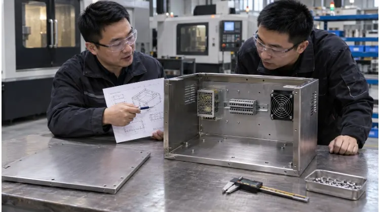
Prototype development is the engineering process of converting a digital CAD design into a physical model to test functionality, fit, and manufacturability. It serves as a crucial risk-management tool to identify design flaws before investing in expensive mass production tooling.
Too many hardware projects face costly delays because they treat prototyping as just “making a physical mockup” rather than a structured path to manufacturing. A successful prototype does not just prove that a concept works on a desk; it proves that the product can be manufactured repeatedly, reliably, and profitably at scale.
The standard workflow is straightforward: define requirements, select the process, manufacture the sample, test and modify, and finally, prepare for mass production.
Quick Reference: Aligning Problems with Prototype Goals
| Current Problem to Solve | Prototype Focus | Expected Outcome for this Round |
| Can the core concept work? | Mechanism or localized test piece | Feasibility assessment |
| Are dimensions and layout appropriate? | Form and space model | Layout revision log |
| Can the product be assembled and function? | Functional prototype | Assembly and performance results |
| Can it be manufactured repeatedly to spec? | Near-production sample | Process and quality confirmation |
Define What Your Prototype Needs to Prove
The objective of this phase is to determine exactly what needs to be built in the current iteration and how to measure its success.
Product Requirements
Start by documenting the product’s intended application, operating environment, mechanical interfaces, and primary functions. Separate non-negotiable requirements from adjustable design preferences. Prioritize identifying features that will dictate structural integrity, specific manufacturing processes, or long procurement lead times.
For example, when designing an industrial equipment chassis, general requirements must be translated into specific engineering parameters. This includes defining the internal clearance for electronic components, the load capacity for heavy door hinges, and the required physical space for maintenance tools.
Prototype Scope
Determine whether this iteration requires a complete assembly, a sub-assembly, or a localized test piece. Prototypes serve different purposes depending on the phase. A Proof of Concept (PoC) validates core mechanisms, while form models test space, and functional prototypes evaluate physical performance.
(Note: While hardware development uses terms like EVT, DVT, and PVT, projects do not always need to follow a rigid, sequential path. Combine testing phases when practical.)
Clearly document what features are included in the current build and what is intentionally left out to save time.
Pass Criteria
Before manufacturing begins, establish the test methods, operating conditions, and acceptable pass criteria. Subjective descriptions like “sturdy” or “easy to assemble” must be converted into inspectable standards. This may involve specifying a maximum deflection limit under load, a specific IP rating for sealing, or a defined torque requirement for fasteners. Assign responsibility for untested requirements to subsequent validation rounds.
💡 Factory Insight: The Cost of Over-Constraining
Avoid over-constraining the prototype. Applying unnecessarily tight tolerances (e.g., specifying ±0.01mm where standard ISO 2768-m is sufficient) will artificially inflate the prototype budget and extend machining time without adding value to the functional test. Only tighten tolerances on critical-to-function interfaces.
Table: Prototype Validation Plan
| Product Requirement | Prototype Scope | Validation Method | Pass Condition | Owner |
| Enclosure heat dissipation | Chassis base + mainboard mock-up | Thermal chamber test | Internal temp stays under 65°C | Thermal Eng. |
| PCB mounting alignment | Base panel only | Physical assembly with standoffs | All 6 mounting holes align without interference | Mech Eng. |
Choose the Process and Plan the Budget
This phase determines the materials, manufacturing methods, sample quantities, and the exact scope of the budget and lead time.
Process Selection
The choice of manufacturing method depends on the specific validation target for the current round.
| Validation Target | Possible Methods | Constraints to Confirm |
| Form, size, and operational space | Simple models, SLA, or other 3D printing | Model accuracy, material brittleness, and usage conditions |
| Specific materials and tight fits | CNC machining or suitable subtractive methods | Fixturing access, precision limits, and inspection capabilities |
| Thin-wall enclosures and brackets | Laser cutting, bending, and fastening | Bend radii limits, material deformation, and assembly sequence |
| Complex internal structures | Additive manufacturing or hybrid assemblies | Post-processing access and surface finish requirements |
| Multiple plastic samples | Vacuum casting, 3D printing, or low-volume molding | Material property differences compared to the final injection molding process |
These applications often overlap. The final decision is driven by a combination of the required structural integrity, material properties, sample quantity, and testing environment.
Material Selection
Evaluate whether a substitute material is acceptable for this testing phase. If the test requires production-grade performance, specify the exact material grade, temper, and condition (e.g., AL6061-T6 instead of generic aluminum).
Record how the properties of substitute materials may skew test results. For instance, using a 3D-printed resin enclosure for a thermal test will not accurately reflect the heat dissipation of the final aluminum part.
A common engineering oversight is designing a prototype around a custom material thickness. Whenever possible, align prototype dimensions with standard stock sizes (e.g., standard sheet metal gauges or bar stock diameters) to avoid significant machining waste and extended material lead times.
Cost and Timing
Prototype costs include more than the unit price of the part. The budget should account for engineering reviews, machine setup, material, temporary tooling, manufacturing, surface finishing, and assembly labor. Determine the required sample quantity based strictly on the testing matrix.
Note that prototype quotes differ significantly from mass production quotes; unit prices become more cost-effective at volume, but initial setups for small batches carry higher proportional costs.
💡 Factory Insight: The “Hidden” Lead Time in Prototyping
When planning the schedule, remember that machining the part is often the fastest step. The most common causes of prototype delays are waiting for custom material delivery and queuing for outsourced surface finishes (like hard anodizing, plating, or powder coating). Always factor in a 20-30% time buffer for external processes.
RFQ (Request for Quote) Checklist:
- Current 3D CAD files (STEP/IGES) and 2D drawings (PDF). (Expert tip: 3D models dictate the geometry for CNC programming, but 2D drawings are critical for communicating tolerances, threaded holes, and critical-to-function dimensions that CAD files cannot convey.)
- Required quantity.
- Specific material grades and acceptable alternatives.
- Surface finish requirements, including masking instructions for critical threads, bearing press-fits, or conductive contact areas.
- Delivery scope (e.g., individual components vs. fully assembled).
- Target delivery date.
Check Manufacturability Before Making the Prototype
The goal of this phase is to identify design issues that will complicate machining, hinder assembly, or drive up costs before any material is cut. A prototype that is easy to make usually translates to a product that is profitable to produce.
Process Constraints
Review the CAD model specifically against the limitations of your chosen manufacturing method. What works for a 3D printer will often fail on a CNC mill or a press brake.
| Manufacturing Method | Typical DFM Checks |
| CNC Machining | Tool access for deep cavities, internal corner radii (avoid sharp inside corners), thin walls, and feasible fixturing setups. |
| Sheet Metal | Minimum bend radii, distance from holes to bend lines, tool clearance for press brakes, and welding sequences. |
| Injection / Die Casting | Uniform wall thickness, sufficient draft angles (usually 1°-3°), parting line locations, and ejection pin placement. |
| Additive (3D Printing) | Build orientation, support structure accessibility, and post-processing limits for critical surfaces. |
(For comprehensive design rules on specific processes, refer to our detailed guides on CNC machining or sheet metal bending.)
Tolerances and Fits
Determine critical dimensions, datums, and fit requirements based on how the parts physically interact. A common engineering error is ignoring tolerance stack-up. If you have a sheet metal chassis, a machined bracket, and a PCB that must align, each part might pass individual quality inspection. However, if all three parts are machined to their maximum allowable tolerance in the same direction, the final assembly may clash or fail to align.
Always confirm the actual machining and measuring capabilities of your manufacturer. Apply tight tolerances only to functional interfaces—like a bearing housing or a mating sealing surface.
Understand that tightening a tolerance from ±0.1mm to ±0.01mm does not just incrementally increase the price; it often requires slower machining feed rates, specialized tooling, and 100% manual CMM inspection, which can triple the cost of that part. Leave non-critical dimensions to standard general tolerances (e.g., ISO 2768-m).
Finishing Requirements
Surface treatments physically alter the dimensions of your part. If you do not account for finishing, assembly will fail.
A standard powder coating layer adds roughly 50 to 100 microns (0.05 – 0.1mm) of thickness per surface. If a machined shaft is designed for a precise slip-fit into a hole, applying a powder coat or thick anodizing layer will prevent the parts from mating. Clearly document masking requirements for tapped holes, grounding points, or press-fit diameters. Explicitly state on your 2D drawing whether the dimensions apply before or after the surface finish.
💡 Factory Insight: The Pre-Production Review (Case Example)
During a DFM review for an aluminum electronics housing, we identified a critical issue: a series of M4 threaded holes were placed too close to a sheet metal bend line. Bending the part would distort the holes, making it impossible to insert the screws.
The Fix: We advised the engineering team to move the holes 3mm further from the bend radius. We also noted that the requested hard anodizing would change the thread pitch, so we added a masking instruction for the threads. These two simple 2D drawing updates prevented an entire batch of prototypes from being scrapped at the assembly bench.
Test the Prototype and Decide What Changes
The purpose of the physical prototype is to generate data. This phase evaluates whether the sample meets the targets defined in Chapter 1 and determines the exact scope of necessary revisions.
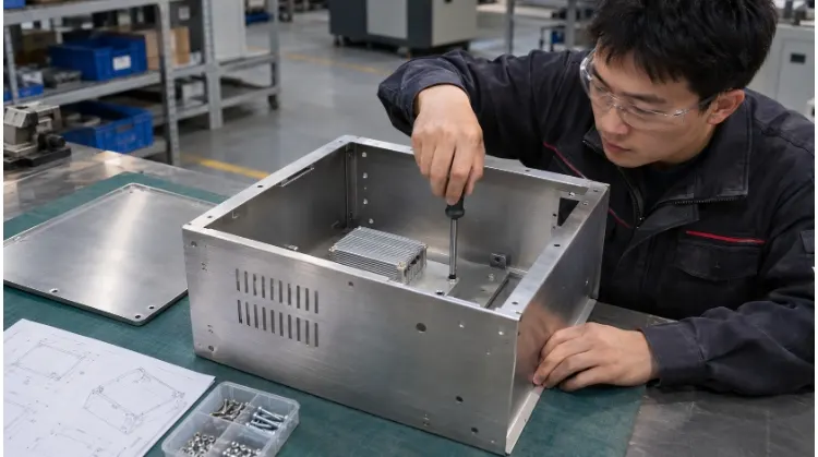
Fit and Assembly
Perform the assembly using the actual production fasteners, cables, and mating components. Check physical interfaces, gap consistencies, and ensure there is adequate physical clearance for assembly tools (like screwdrivers or wrenches). Verify cable routing paths and assess how easily the unit can be disassembled for maintenance.
Pay strict attention to manual adjustments on the bench. On the shop floor, it is common to grab a hand file or a drill to widen a tight hole so the prototype fits together. Record every manual modification. If you file down a bracket to make it work but fail to update the CAD model, the mass-production batch will arrive with the exact same flaw.
Functional Performance
Execute the testing plan under the conditions defined earlier. Depending on the product, this may involve load testing, thermal cycling, IP-rating water tests, or cycle durability. Log the specific prototype version, the testing environment, the results, and any anomalies. Keep internal developmental testing separate from formal regulatory certification (like UL, CE, or FCC). Failing an internal drop test is a design iteration; failing a formal lab certification is a costly delay.
Beware the “Process Translation Trap.” A prototype CNC-machined from a solid block of AL6061 will have different tensile strength and fatigue limits than the final mass-production part made via High-Pressure Die Casting (e.g., ADC12). Always account for these material property shifts when reviewing test data to determine production readiness.
Revision Decisions
Compare the physical test results directly against your initial pass criteria. When a failure occurs, determine the root cause: is it a fundamental design flaw, a manufacturing deviation by the prototype shop, or a flawed test setup?
Evaluate how modifying the design will impact other functions, unit cost, and production tooling lead times. Update the master CAD files and BOM, and decide which specific features require a second round of prototyping for verification.
Table: Prototype Revision Log
| Problem Identified | Root Cause Analysis | Modification Implemented | Impact on Production | Retest Result |
| Enclosure door binds during opening. | Hinge mount deflected under the weight of the door. | Added a sheet metal gusset (rib) to the hinge bracket in CAD Rev B. | Negligible. Only requires updating the laser cut flat pattern. | Door opens smoothly. Passed. |
| PCB overheating (>75°C) during load test. | Inadequate airflow near the power supply module. | Increased vent hole diameter from 3mm to 4mm. | Low. Simple CNC tool path update. No custom tooling needed. | Peak temp stabilized at 62°C. Passed. |
| M3 screws stripped during assembly. | Threads were coated during the painting process. | Updated 2D drawing to mandate masking for all threaded holes. | None on tooling. Standardizes the surface finish process. | Screws thread smoothly by hand. Passed. |
Confirm the Design Is Ready for Production
The final phase of prototype development is translating an approved physical sample into repeatable, scalable manufacturing instructions. The goal is to ensure the factory can produce the 1,000th unit exactly like the approved prototype.
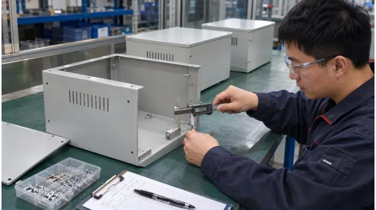
Approved Documents
Once a prototype passes all validation tests, the engineering data must be locked down. This is commonly referred to as the “BOM Freeze.” Unify your 3D CAD files, 2D drawings, Bill of Materials (BOM), and the physical “Golden Sample” so they all reflect the exact same revision.
If a technician manually enlarged a clearance hole on the bench to make the prototype fit together, that change must be permanently written into the final CAD file. Solidify the material grades, surface finish specifications, assembly sequences, and quality acceptance criteria. If minor open issues remain, explicitly document who is responsible for closing them and by what date. Make it absolutely clear to the manufacturer which specific file revision is approved for production.
Supply Readiness
A perfect prototype is useless if you cannot source the parts at scale. Verify the supply conditions for raw materials, standard hardware, and key components. Confirm the Minimum Order Quantities (MOQs), standard material lead times, and acceptable alternative components.
(Note: If you swap a component for a faster-lead-time alternative, ensure the substitute undergoes its own functional verification to confirm it does not alter product performance.)
Clarify the quality control boundaries with your manufacturer. Define who is responsible for incoming material inspection, how manufacturing deviations will be reported and approved, and the procedure for Engineering Change Notices (ECNs). Establish clear agreements on document confidentiality (NDAs). Most importantly, explicitly state who retains ownership and transfer rights of any custom molds, welding jigs, or machining fixtures paid for during the setup phase. Prevent “tooling hostage” situations before they happen.
Pilot Production
Never jump straight from a single prototype to a full-scale mass production run. Execute a Pilot Run (often called NPI – New Product Introduction) of a small batch, typically 50 to 100 units.
This batch must be built using the exact materials, manufacturing processes, custom tooling, and standard operating procedures intended for mass production. Do not use the prototype shop for this run. The objective is to check manufacturing consistency and process stability. Identifying a 10% defect rate or an assembly bottleneck in a 50-unit pilot run costs a fraction of discovering it during a 5,000-unit mass production run.
Track the assembly cycle time, identify steps that cause operator bottlenecks, and log any recurring rework issues. Based on the yield rate and dimensional consistency of this pilot batch, decide whether to authorize full-scale production, refine the assembly process, or run a second pilot.
Production Release Checklist:
- Document Alignment: Do the 3D CAD, 2D PDF, and BOM perfectly match the approved revision?
- Golden Sample: Is a signed, physical prototype retained by both the client and the factory QA department for reference?
- Supply Chain: Are raw material lead times, MOQs, and component alternatives confirmed?
- Process Definition: Are finishing standards, masking rules, and assembly instructions documented?
- Open Issues: Are all critical design deviations and testing failures officially closed?
Ready to Transition from Prototype to Production?
Moving from a digital design to a repeatable manufacturing process requires strict DFM control and transparent communication. At TZR, we specialize in custom CNC machining and precision sheet metal fabrication, bridging the gap between prototyping and mass production.
We don’t just blindly quote your drawings. Our engineering team actively reviews your CAD files, provides actionable DFM feedback to eliminate hidden cost drivers, and ensures your product scales reliably. Send us your 3D CAD and 2D drawings today for a comprehensive DFM review and an accurate manufacturing quote.